MAINTENANCE
109
4. On the 195ADC chassis, remove the
Snubber PCB, the AC bus bars, and the
appropriate DC bus bar to gain access
to the SCR modules. Save all
hardware, as it will be needed for re-
assembly. Screw lengths are important.
5. RRemove each defective SCR module,
taking care not to scratch or burr the
heat sink surface. Remove and discard
the coated aluminum thermal wafer, if
present. Save all screws and washer
hardware. It will be needed in the
proper order for re-assembly. Remove
the gate & cathode lead assembly from
the defective module.
6. To install new SCR module(s), ensure
that the heat-sink surface and bottom of
the SCR module is clean and free from
any dirt. Install a new thermal wafer by
first removing the protective paper
coating and lining it up with the
mounting holes on the heat-sink. A thin,
even coating of thermal joint compound
applied to the bottom of the SCR
module may be used instead of the
thermal wafer. Position the module on
the heat sink and loosely install the
mounting screws with washers. Do not
tighten mounting screws more than
finger tight at this time.
7. Apply a thin coating of Joint-Al-Z on all
mating electrical surfaces and replace
all bus bars. Start all hardware screws
making them finger tight., Ensure
proper alignment of all components,
then torque bus bar mounting screws to
26 inch-pounds.
IMPORTANT
DO NOT
use a torque wrench to tighten
SCR module mounting hardware. The
correctly flattened Belleville washer as
described below provides the proper
mounting pressure.
8. Now tighten the mounting hardware for
any replaced SCR modules: Tighten
each screw equally and alternately, ¼
turn at a time. Continue with this
procedure until the Belleville washers
become flat. An abrupt change in
torque will be detected when the
Belleville becomes flat.
9. Reinstall the AC and DC bus bars.
Tighten bus bar mounting screws until
Belleville washers become flat.
10. Reinstall the two power lead wires
feeding the Field Interface PCB, if they
were previously removed.
11. Reinstall the Armature Interface PCB
and the Snubber PCB. Torque the
mounting screws to 10 inch-pounds. All
mounting screws must be in place for
proper operation.
12. Reconnect each of the SCR gate and
cathode leads to the Armature Interface
PCB at plugs J30-32 and J34-36. If the
gating leads were removed from the
SCR module, the white gate leads go
directly down to the SCR module pins
closest to the end of the module. No
wires cross.. If the assembly had red
cathode leads, those leads plug into the
SCR modules next to the gate leads.
13. Reconnect wires going to A2TB5-1 and
A2TB5-2. Reinstall plugs at J24, J27,
and J29.
14. Verify and reinstall fuses.
Cooling Fan Replacement
The cooling fan is located inside a plenum
box near the bottom of the chassis.
Remove 2 screws from each side of the
chassis for access. The 115VAC supply
plugs into the side of the fan motor.
Thermistor Replacement
The thermistor connects to the Armature
Interface PCB at J28. It is located on the
heat sink. Remove the Armature Interface
PCB for replacement access. Place a light
coating of thermal grease or Joint-Al-Z on
bottom side of the thermistor before re-
assembly.
Current Transducer Replacement
The Armature Current Transducer is
mounted on the left side where the buss bar
can pass through it. Remove the Armature
Interface PCB for replacement access.
Remove the DC output buss bar. Two
screws on the chassis side-wall hold the
transducer in place.
Summary of Contents for DSD 412
Page 1: ...DSD 412 DC Elevator Drive Technical Manual CS00407 rev 06...
Page 6: ...6...
Page 102: ...MAINTENANCE 102 Figure 24 Connector and E prom Locations...
Page 103: ...MAINTENANCE 103 Figure 25 Test Point Locations...
Page 115: ...OUTLINE DRAWING 100A 115 Figure 26 Drive Chassis Outline DSD 412 100 Amp...
Page 116: ...OUTLINE DRAWING 190A 116 Figure 27 Drive Chassis Outline DSD 412 195 Amp...
Page 117: ...OUTLINE DRAWING 300A 117 Figure 28 Drive Chasis Outline DSD 412 300 Amp...
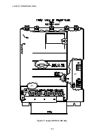
Page 118: ...LAYOUT DRAWING 100A 118 Figure 29 Layout DSD 412 100 Amp A3 A1 A2 A2 L1 NEG GND L2 L3 POS...
Page 119: ...LAYOUT DRAWING 195A 119 Figure 30 Layout DSD 412 195 Amp A3 A1 A2 A2...
Page 120: ...LAYOUT DRAWING 300A 120 Figure 31 Layout DSD 412 300 Amp A3 A1 A2 A2...
Page 121: ......


