background image

31

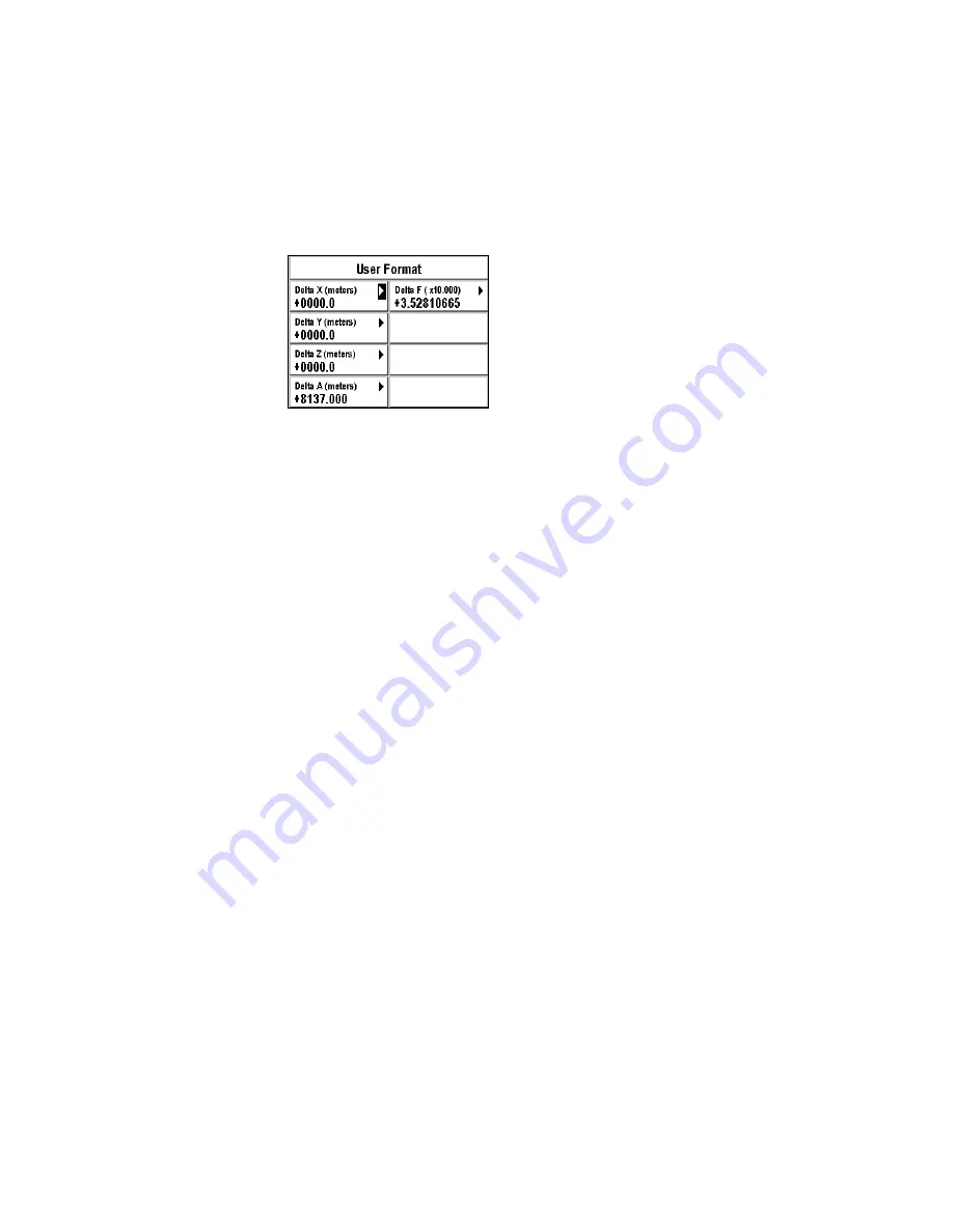
For each window, enter the desired value using the alphanumeric keypad 
and push Enter. 

Note: 

Hold the 1 button down to enter a + or - sign. 

‰

Choosing 2D or 3D Mode 

Your FX324 MAP can calculate your position in two dimensions (latitude 
and longitude), or in three dimensions (latitude, longitude and altitude). 

The 2D/3D Mode option lets you select the mode you wish to use. 

Menu

Æ

 POS Tab 

Æ

 5-2D/3D Mode

Select Auto and then push Enter if you want your position to be calculated 
in 3 dimensions whenever 5 or more satellites are visible. 

Select 2D and push Enter if you want your position to always be 
calculated in two dimensions. The window is redisplayed so that you can 
enter a fixed altitude. Enter the altitude using the alphanumeric keypad 
and push Enter. 

Select 3D and push Enter if you want your position to always be 
calculated in three dimensions, even if less than 5 satellites are visible. 

Advice:  

When using the device for boating, choose the 2D mode and enter 
the elevation of your device with respect to the mean sea level. If 
you have an external antenna, enter the height of the antenna with 
respect to the mean sea level.  

Summary of Contents for FX324 MAP

Page 1: ...government and may change according to the U S Department of Defense s policy on private GPS use Accuracy may also be compromised by poor satellite geometry It is the user s responsibility to verify...
Page 2: ...disassembling or transmitting this software is prohibited except for needs that are expressly authorized in this license All rights that are not expressly authorized are reserved for Thales Navigation...

Page 3: ...6 Setting the Local Time ___________________________________________________ 17 Choosing the Units of Measurement ________________________________________ 17 Unit of Distance and Speed _______________...

Page 4: ...__________________ 36 Choosing the Unit of Cross Track Error XTE _____________________________ 37 Choosing the Unit of Depth ___________________________________________ 37 Setting Alarms _____________...

Page 5: ...______________________________________ 68 Displaying the Vessel Line ____________________________________________ 68 Displaying the Waypoints ____________________________________________ 68 Displaying...

Page 6: ...ain terms used ______________________________________________ 87 Automatic Switch to the Next Waypoint in a Route _____________________________ 90 Version and Serial Number ___________________________...

Page 7: ...ce and keeping constant watch However your FX324 MAP is equipped with comprehensive software that provides all the information that is indispensable for navigation and remains very easy to use Its 8 f...

Page 8: ...section will enable you to get to know your device and we recommend that you read it carefully before using the equipment Views of the Device General View of the Device Front Mounting Bracket Alphanum...

Page 9: ...General View of the Device Back Power On and Off Power On Push the PWR button to turn on your GPS You will hear a beep and the following screen will appear Extenal Antenna Power Data Cable Knob Washe...

Page 10: ...sition screen Your position is displayed after a few minutes the time it takes to make the first calculation The first time you use your FX324 MAP you will have to make a certain number of configurati...

Page 11: ...you to follow your position and your route on the chart Push the button a second time to display the second Plotter screen 0 9 Keypad that allows you to enter alphanumeric values Hold the button down...

Page 12: ...t you can select actions or options The Esc button will cancel a selection or return you to the previous screen Selecting an Option in a Menu Push the Menu button to access the various menus on your F...

Page 13: ...reen push the Esc button Selecting an Action The actions that can be selected are displayed in black red or dark blue for the FX324 MAP Color To select an action highlight its icon or its text using t...

Page 14: ...he Position Navigation GoTo and Plotter screens that display the symbol are configurable They have a list from which you can choose the type of information displayed Example On the GoTo screen below t...

Page 15: ...t indicates the direction your vessel is drifting Course The angle formed by the course direction and reference north Your course over the ground is constantly updated Bearing Angle in degrees between...

Page 16: ...destination waypoint The letter R Right or L Left indicates whether your vessel is to the right or left of the direct line between your starting position and your destination waypoint CPE Acronym for...

Page 17: ...Type the day with the alphanumeric keypad Select the month using the and arrows on the button Go to the Year field using the arrow on the button Type the year using the alphanumeric keypad Enter the d...

Page 18: ...r Note An action for which the icon is displayed in black can be selected red for the FX324 MAP Color an action for which the icon is displayed in gray light blue for the FX324 MAP Color cannot be sel...

Page 19: ...nd is always highlighted on the Navigation menu Cross Track Error Alarm Is highlighted on the Navigation menu when the alarm is activated Speed Alarm Is highlighted on the Navigation menu when the ala...

Page 20: ...rast and backlighting Push the PWR button briefly to display the following window Backlighting Select the Light setting bar with the and arrows on the button Then select the desired level of backlight...

Page 21: ...Contrast setting bar with the and arrows on the button Then select the desired level of contrast with the and arrows on the button The far left of the bar represents the highest level of contrast and...

Page 22: ...he following window appears allowing you to select your display language Browse the scrolling list with the button and select the desired language by pushing Enter You can change the language in which...

Page 23: ...e alphanumeric keypad and push Enter See Setting the Local Time or a Date Note The local time must be entered in 24 hour format Choosing the Units of Measurement The Navigation menu enables you to sel...

Page 24: ...levation Unit The available units of measurement include Meter Feet Feet 0 3048 Meter Select a unit from the list and push Enter Cross Track Error XTE Unit To change the unit of measurement for the cr...

Page 25: ...d German G Position in German Grid Swedish G Position in Swedish Grid Finnish G Position in Finnish grid USER User Format Select a system of coordinates from the list and push Enter Note You can creat...

Page 26: ...fault parameters and settings To restore your FX324 MAP settings as they were when you used it for the first time Menu SETUP Tab 7 Default configuration Select Yes and push Enter to accept the warning...

Page 27: ...ition in the chosen system of coordinates your speed your course over the ground your CPE the date and the local time The satellite symbol means that your position has been entered and calculated The...

Page 28: ...g the Information Displayed in the Configurable Window Date and Time Satellite Symbol WAAS EGNOS MSAS Symbol The date and local time are always displayed The satellite symbol means that your FX324 MAP...

Page 29: ...MapSend BlueNav Charts Tide Tab This tab displays the times for high and low tides the water height and the coefficients for a selected date and port coefficients are available only for French intern...

Page 30: ...choose a port from among the list of 896 worldwide ports in the memory of your FX324 MAP or select MapSend BlueNav Port to choose a port from the loaded chart See Selecting a value from a list and Ma...

Page 31: ...Position TIDE Tab GRAPH Enter Example On the following screen the water height at the port of Lorient on 20 August 2002 at 9 45 a m is 5 24 feet above the height of water at Lowest Astronomical Tide U...

Page 32: ...ts direction with regard to True North will be 197 degrees The maximum current of the falling tide will occur at 12 36 a m and 1 02 p m its speed will be 1 99 knots and its angle will be 14 degrees Th...

Page 33: ...every 15 minutes HDR Tab True Heading Repeater You can connect your FX324 MAP to a true heading sensor such as the 3011 GPS Compass from Thales Navigation If you have connected your GPS to a compass t...

Page 34: ...s the accuracy of the calculated position at any time Menu POS Tab 1 Satellites Example The screen below shows that the GPS receives 10 satellites The CPE is equal to 2 meters and the DOP is equal to...

Page 35: ...PE is 2 meters your actual position is 50 likely within a radius of 2 meters from the calculated position Note Because of the position of the satellites always above the accuracy of the altitude calcu...

Page 36: ...ed value using the alphanumeric keypad and push Enter Note If you hold the 1 button down you can enter a or sign Choosing the Map Datum The Map Datum option allows you to change the format of the char...

Page 37: ...ated in 3 dimensions whenever 5 or more satellites are visible Select 2D and push Enter if you want your position to always be calculated in two dimensions The window is redisplayed so that you can en...

Page 38: ...once or twice Example The screen below displays your speed in knots your course in degrees two distance counters in nautical miles and your cross track error XTE in nautical miles Note If the screen...

Page 39: ...ted See Choosing the Information Displayed in the Configurable Window Date and Time Satellite Symbol WAAS EGNOS MSAS Symbol The date and local time are always displayed The satellite symbol means that...

Page 40: ...r A confirmation message is displayed Select Yes and push Enter to confirm that you want to reset the Maximum Speed to zero or select No and push Enter to cancel Chronometer To start the chronometer N...

Page 41: ...he icon and push Enter to begin the countdown Select the icon and push Enter to stop the countdown Average Speed Trip Time Distance Traveled Your average speed is displayed in the selected unit of mea...

Page 42: ...ing Menu and then the NAV Tab Seven options are available See Navigating through the Screens and Selecting Options Choosing Units of Distance and Speed The Distance Unit option allows you to select th...

Page 43: ...measurement for the depth of water in the ports and on the charts Menu NAV Tab 4 Depth Unit The available units of measurement include Meter Feet Feet 0 3048 Meter Select a unit from the list and pus...

Page 44: ...ng to be traveled becomes less than the specified value For example if you define the arrival alarm to sound at 1 mile it starts sounding when you approach the waypoint within one mile Note When this...

Page 45: ...tion of the alarm beep Menu SETUP Tab 1 Alarms Beep Select the type of beep from the list and push Enter If you choose the Continuous option the beep sounds until you press a button Defining Reference...

Page 46: ...The Compass mode screen below displays the course being followed and the bearing to arrive at the waypoint FASTNET The three configurable windows on the left of the screen display your speed the beari...

Page 47: ...ed at the bottom of the screen Advice To quickly access a desired waypoint enter the first letter s of its name in the active field The list is updated with all the waypoint names that begin with that...

Page 48: ...the following example your route is made of three waypoints A B and C Point X is the current position of your vessel When activating the route the destination waypoint is waypoint B and A is considere...

Page 49: ...sing the button and push Enter The list of services that are available at that port is displayed in the form of a bar of icons Fuel Water Other Services Repairs General Services First Aid Information...

Page 50: ...To function To advance to the next waypoint in an active route GoTo icon Enter The name of the new active waypoint is displayed at the bottom of the screen Perform the operation again to advance anoth...

Page 51: ...D Road Mode Select the icon with the button and push Enter until the 3D Road mode is displayed on the screen The black line represents the direction to follow to reach the destination waypoint It pivo...

Page 52: ...tance remaining is less than 1 kilometer 2 The length of the road represents a maximum of 2 kilometers The destination waypoint icon is displayed at the end of the road if the distance remaining is le...

Page 53: ...mode all of the displayed information can be configured Select any window using the button push Enter and select the desired type of information from the list Push Enter to choose your selection Confi...

Page 54: ...gnor Regis Note If the screen that is displayed after pushing the GoTo button is different push the GoTo button once again Waypoint No 1 Select the upper left window using the button and push Enter to...

Page 55: ...aypoint to the second waypoint Note All bearings calculated by your device represent the shortest distance between two points great circle Waypoint Menu The Waypoint menu can be displayed directly by...

Page 56: ...ansferring Files The name of the waypoint the icon that is associated with it its coordinates as well as any comments you may have added optional are displayed The date and time the waypoint was creat...

Page 57: ...e date and the time of the modifications are automatically recorded Note An active waypoint or a waypoint used in a route cannot be amended This is also true for the ANCHOR and MOB waypoints Deleting...

Page 58: ...the 2 button down the letters a b and then c will appear Once you have typed the letter or number the cursor automatically advances to the next space If you make a mistake use the and buttons on the...

Page 59: ...waypoint or passage point by pushing the Mark MOB button See Using the Man Overboard MOB and the Mark Functions Recording a Waypoint with the Cursor From the Plotter screen the Cursor mode allows you...

Page 60: ...T Tab 4 Delete All A confirmation message is displayed Select Yes and push Enter to delete all waypoints Select No and push enter to return to the menu without deleting them When using this option the...

Page 61: ...f all your routes You cannot select this option if your list of routes is empty Menu RTE TRK Tab 1 Route List Note The list of your routes can be transferred to or from your SD Card See Transferring F...

Page 62: ...that for creating a route You must select using the button and push Enter to save the changes you have made See Creating a Route Delete a Route Select using the button and push Enter to delete the rou...

Page 63: ...and push Enter The name of the selected waypoint displays at position 01 Push Enter again to select the second waypoint in your route Advice To quickly access a desired waypoint enter the first lette...

Page 64: ...the end of a route Select using the button and push Enter to add a new waypoint to the end of your route Select using the button and push Enter to insert a new waypoint before the waypoint that you ha...

Page 65: ...he Track List option allows you to view your list of tracks Menu RTE TRK Tab 5 Track List Note The list of your tracks can be transferred to and from your SD Card See Transferring Files To and From Yo...

Page 66: ...selected track on the Plotter screen See Locating Your Position and Course Select using and push Enter to delete the selected track Select using and push Enter to select a track by moving toward the t...

Page 67: ...or No inactive and push Enter Select Yes to automatically create and activate a route enabling you to go back to your starting point following the same itinerary Choosing the Track Interval Option 7...

Page 68: ...sel is represented by an isosceles triangle whose point corresponds to your course and your track is represented by a dotted line The two hachured lines represent the direct line and the mobile to way...

Page 69: ...aids See Plotter Menu and Chart Menu Centering the Screen on a Waypoint You can press the 5 button on the alphanumeric keypad at any time to display your list of waypoints and select the one you want...

Page 70: ...been activated in the Plotter menu the OVERZOOM indicator appears when the selected zoom scale makes it impossible to display the chart with a good definition If the Over zoom mode has not been activa...

Page 71: ...then select on the route sheet and push Enter to save it This route can be activated edited or deleted as any other route See Route and Track Menu Note You can view the data for each waypoint in the...

Page 72: ...ed on the left of the screen can be configured Select a window and push Enter to choose the type of information you would like to view from the list Push Enter to choose your selection See Choosing th...

Page 73: ...h Enter North up North is always at the top of the screen Direct Line Up sometimes called Course Up The destination waypoint is always at the top of the screen Course Up sometimes called Track Up The...

Page 74: ...direct line to your destination waypoint Menu PLOT Tab 4 Direct Line Select Yes visible or No invisible and push Enter Displaying the Vessel Line You can choose whether or not to display the line bet...

Page 75: ...a good definition If the Over zoom mode is not active only the zoom scales allowed by the loaded chart are available Menu PLOT Tab 8 Over zoom Select Yes active or No inactive and push Enter Note You...

Page 76: ...7 MapSend BlueNav Demo Enter Chart Menu The Chart menu can be displayed by pushing Menu from any screen and then selecting the CHART tab Seven options are available eight for the FX324 MAP Color See N...

Page 77: ...played in grayscale on the FX324 MAP and in color on the FX324 MAP Color Displaying Light Sectors You can choose whether or not to display the signal light sectors that is whether or not the different...

Page 78: ...g the Color Palette You can choose the color palette used for the display Menu CHART Tab 8 Color Palette Select one of the three palettes and push Enter Note This option is only available on the FX324...

Page 79: ...Only Mode When the MOB mode is selected you only need to push the Mark MOB button once to activate the Man Overboard function The Mark MOB function allows you to activate the MOB only mode Menu SETUP...

Page 80: ...Alarm is activated Note The ANCHOR waypoint can be viewed but cannot be edited or deleted like other waypoints It is automatically replaced the next time the Mark MOB function is used with the Anchori...

Page 81: ...MOB and push Enter Your current position as well as the time and date are immediately recorded in the form of a waypoint called MOB and the point is assigned an icon representing a target The MOB wayp...

Page 82: ...ng it out of the reader Warning We recommend you turn off your FX324 MAP when installing or removing a SD Card Failure to do so may cause dysfunction insert the new SD Card with the logo facing you wi...

Page 83: ...to transfer files from your FX324 MAP to your SD Card transfer files from your SD Card to your FX324 MAP delete files select the type of file to be transferred select the type of file to be transferr...

Page 84: ...tivate the navigation simulator Menu ADVAN Tab 3 Simulator Coordinates Select this window and push Enter to input a position Speed Select this window and push Enter to input a speed Course Select this...

Page 85: ...through its serial output in BWC sentences NMEA 183 1 5 2 0 or 2 3 standard See Digital Output and NMEA Digital Input If the formats and connections are correct the name of the waypoint received is di...

Page 86: ...ferential receiver You should follow the following connection table Description FX324 MAP FX324 MAP Wires DF300 Receiver Wires 0 volts Blue Blue 10 to 36 volts DC Red Red RS422 Reference Orange Yellow...

Page 87: ...the DF300 from your FX324 MAP the serial output port must be in NMEA 183 1 5 or NMEA 183 2 0 or NMEA 183 2 3 format and the PML3 and MSK sentences must be selected for this format Menu SETUP Tab 3 Se...

Page 88: ...en functioning in DGPS mode Corrected Satellites The list of corrected satellites Station The identification number of the DGPS station Note When the FX324 MAP functions in differential mode the lette...

Page 89: ...rubber washer between the receiver and the knob Connect the Power Data cable to the back of your receiver Place your receiver into the notches on the arms of the bracket place the washer between the d...

Page 90: ...o the device placing a washer and a nut between the bulkhead and the head of each screw When the screws have been screwed in all the way turn the nut against the bulkhead to firmly attach the device C...

Page 91: ...and the red wire to the If you need to replace the safety fuse always use a fuse with the following characteristics Type 6 3x32 Fast blow 2A 250V UL CSA Date Output or Digital Output The FX324 MAP is...

Page 92: ...brand FX324 MAP compatible antenna or if unavailable an MLR brand ANTGPS15 antenna The position of the antenna must be chosen such that the length of the coaxial cable does not exceed 10 meters The a...

Page 93: ...Position of the Vessel D Course E Bearing J Course Correction A B Direct Line to the Destination Waypoint C B Distance to the Destination Waypoint C D Cross Track Error XTE C E Speed C F Velocity to...

Page 94: ...estination waypoint This angle is referenced with respect to magnetic or true north depending on the reference north chosen Angle E Course Correction The correction to be made to the course in order t...

Page 95: ...5 meters from the calculated position Coordinates Unique alphanumeric description of your position on the globe Map datum Theoretical mathematical model representing the surface of the earth The forma...

Page 96: ...D and the other is smaller than 180 angle The change of active waypoint occurs differently depending on the angle the vessel is moving in Vessel moving in the angle greater than 180 angle D The chang...

Page 97: ...ple NMEA 180 format for autopilot 8 bits of DATA bit D7 0 bit D6 01 STOP bit 1200 BAUDS even parity 4 sec frequency The message includes a single byte where D0 to D5 indicate the cross track error in...

Page 98: ...al circle Radius in NM Version 1 5 C C Waypoint identification in 4 letters Version 2 0 and Version 2 3 C C Waypoint identification in 6 letters hh Sentence checksum APB Autopilot format B Version 1 5...

Page 99: ...W 269 T 269 M 1 36 N C C hh Version 2 3 GPBWC 150858 4710 75 N 00117 61 W 269 T 269 M 1 36 N C C a hh 150858 UTC time 4710 75 N 00117 61 W Latitude and longitude of the destination fix in hundredths o...

Page 100: ...y if the fix is calculated in differential mode ZZZZ Differential reference station identification only if the fix is calculated in differential mode Version 2 3 Y GPS quality indicator 0 fix not calc...

Page 101: ...60 W 080523 A V hh Version 2 3 GPGLL 4710 74 N 00115 60 W 080523 A V a hh Version 2 0 080523 UTC time A V Valid fix A invalid V hh Sentence checksum Version 2 3 080523 UTC time A V Valid fix A invali...

Page 102: ...ion 2 3 GPGSV X X XX XX XX XXX XX XX XX XXX XX hh X Total number of messages 1 to 3 X Message number 1 to 3 XX Total number of satellites in view XX Satellite number XX Altitude in degrees XXX Azimuth...

Page 103: ...ation in knots A V Arrival circle entered or perpendicular passed at waypoint hh Sentence checksum Version 1 5 W W Identification of the original waypoint in 4 letters C C Waypoint identification in 4...

Page 104: ...n of the functioning mode of the DGPS A Autonomous B Differential C Simulator D Non valid data VTG Track made good and ground speed Version 1 5 GPVTG 134 T 000 M 000 0 N 000 0 K Version 2 0 GPVTG 134...

Page 105: ...onomous B Differential C Simulator D Non valid data hh Sentence checksum ZDA Date and time Version 1 5 GPZDA 070252 08 04 1998 XX Version 2 0 and Version 2 3 GPZDA 070252 08 04 1998 XX YY hh 070252 UT...

Page 106: ...m PML5 Coordinate grid PML5 XXXXXXXXXX 4710 7056 N 00115 6984 W hh 4710 705 N Latitude N S 00115 698 W Longitude E W XXXXXXXXXX 1 10000MIN for latitude and longitude in thousandths of a minute XXXXXXX...

Page 107: ...uthorized 1 alarm authorized d f h j l n p r alarm status 0 inactive alarm 1 one or several active alarms hh sentence checksum PML7SN Serial number PML7 SN 01 XXXXXXXXXX hh CR LF Where XXXXXXXXXX is t...

Page 108: ...m Route information PMGNRTE xx xx c n c c c c c c c c c hh This message is used to transmit route information from and to your GPS unit The message consists of two groups of fields The first set of fi...

Page 109: ...llowed by E or W The next field is the altitude followed by F for Feet or M for Meters The next field is the UTC time of the fix The next field consists of a status letter of A to indicate the data is...

Page 110: ...d Velocity to the destination waypoint and drift speed 2 distance traveled counters logs Time and distance to destination waypoint Chronometer and countdown 1000 waypoints with names of 8 alphanumeric...

Page 111: ...rts around the world local ports on the chart Ephemeris Sunrise and sunset moonrise and moonset Repeater for external GPS compass Master Slave function MOB function activation via NMEA input Battery v...

Page 112: ...m technology ensuring that all navigation waypoint route and other information is saved for 100 years Receiver dimensions 230 x 136 4 x 61 mm 9 x 5 4 x 2 4 1 RS422 output NMEA 1 RS232 output NMEA 1 RS...

Page 113: ...ens contain small quantities of mercury The FX324 MAP and FX324 MAP Color meet the requirements of the European Council directives R TTE 1999 5 CE 89 336 EEC 73 23 EEC and also meet the requirements o...

Page 114: ...t Thales Navigation will at its option repair or replace the hardware product with no charge to the purchaser for parts or labor The repaired or replaced product will be warranted for 90 days from the...

Page 115: ...s receipt is not provided or if the information contained in it is incomplete or illegible or if the serial number is altered or removed Thales Navigation will not be responsible for any losses or dam...

Page 116: ...cur due to changes in the position health or geometry of a satellite or modifications to the receiver that may be required due to any change in the GPS Note Thales Navigation GPS receivers use GPS or...

Page 117: ...the goods and any and all warranties and representations THIS WARRANTY SETS FORTH ALL OF THALES NAVIGATION S RESPONSIBILITIES REGARDING THIS PRODUCT THIS WARRANTY GIVES YOU SPECIFIC RIGHTS YOU MAY HAV...

Page 118: ...2 For further information concerning this limited warranty please call or write Thales Navigation SA ZAC La Fleuriaye BP 433 44474 Carquefou Cedex France Phone 33 0 2 28 09 38 00 Fax 33 0 2 28 09 39 3...

Page 119: ...pment or for the balance of the original warranty whichever is longer Thales Navigation warrants that software products or software included in hardware products will be free from defects in the media...

Page 120: ...or if the information contained in it is incomplete or illegible or if the serial number is altered or removed Thales Navigation will not be responsible for any losses or damage to the product incurr...

Page 121: ...be required due to any change in the GPS Note Thales Navigation GPS receivers use GPS or GPS GLONASS to obtain position velocity and time information GPS is operated by the U S Government and GLONASS...

Page 122: ...G THIS PRODUCT THIS WARRANTY GIVES YOU SPECIFIC RIGHTS YOU MAY HAVE OTHER RIGHTS WHICH VARY FROM LOCALITY TO LOCALITY including Directive 1999 44 EC in the EC Member States AND CERTAIN LIMITATIONS CON...

Reviews: