background image

D i g i t a l  8 • B u s

34

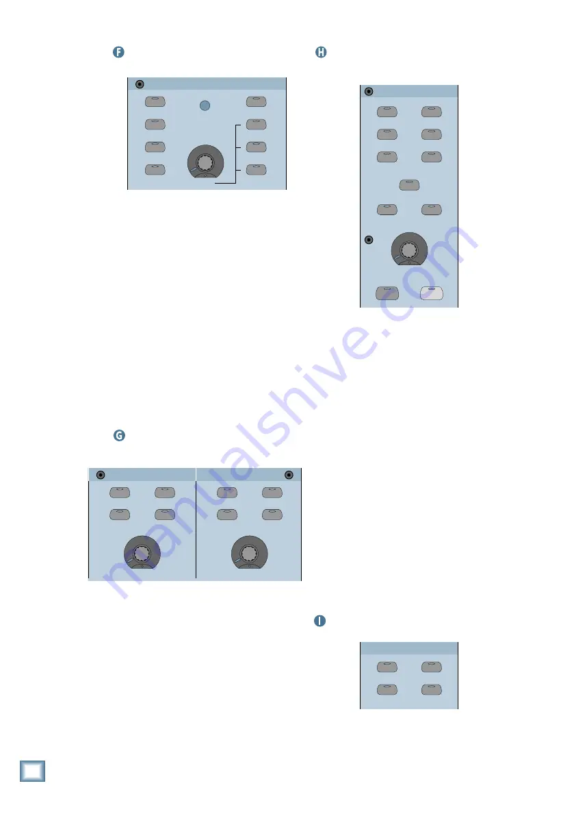
 Studio/Solo Section

STUDIO/SOLO

SOLO LEVEL

STUDIO LEVEL

CLEAR SOLO

TALKBACK TO

STUDIO

AFL SOLO

PFL SOLO

MIXDOWN SOLO

TALKBACK LEVEL

LEVEL

RUDE SOLO

LIGHT

This section contains a V-Pot to control sev-

eral different functions. When SOLO LEVEL is
selected, the V-Pot controls the solo bus signal
level. When STUDIO LEVEL is selected, it con-
trols the signal level at the STUDIO OUT jacks.
When the TALKBACK LEVEL button is selected,
it controls the level of the Talkback Mic. Use
the PFL SOLO button and AFL SOLO to choose
between pre-fader and post-fader soloing.

The TALKBACK TO STUDIO button directs

the Talkback Mic signal to the STUDIO
OUTputs. The CLEAR SOLO button provides a
quick way to turn off all the SOLO buttons on
the console.

Normally, when a channel is soloed, it af-

fects only the Control Room Outputs, and not
the Main outputs. Pressing the MIXDOWN
SOLO button allows you to solo channels in the
L-R Main Outputs.

 Phones/Cue Mix 1 and 2 Section

This is where you select the source for the

Phones outputs and set the Phones levels.
Press CONTROL ROOM to send the signal at
the Control Room outputs to the Cue Mix,
press AUX 9–10 to send the signal at the Aux
9–10 output to the Cue Mix, and press AUX
11–12 to send the signal at the Aux 11–12 out-
put to the Cue Mix. The COPY MIX TO CUE
button copies all the fader levels on channels
1–48 to each channel’s V-Pot, for the Aux Send
selected in the Phones/Cue Mix Section. Use
the V-Pot in the Phones/Cue Mix Section to ad-
just the level at the PHONES output.

 Control Room Section

2 TRACK A

DIGITAL IN 1

2 TRACK B

DIGITAL IN 2

2 TRACK C

MASTER

L-R

NEAR FIELD

MAIN

DIM

TALKBACK

CONTROL ROOM

SPEAKER LEVEL 

MONO


SPEAKERS 

This is where you select the signal source

and adjust the output level for the control room
outputs. Press 2 TRACK A, B, or C to select
one of three 2-track sources. Press DIGITAL
IN 1 to select the AES/EBU Input, and DIGI-
TAL IN 2 to select the S/PDIF Input as the
control room source, and press L-R to select
the L-R bus.

The NEAR FIELD and MAIN buttons are

used to select either the CR NEAR FIELD out-
put or the CR MAIN output. When MONO is
selected, the stereo Control Room signal is
summed into a monaural output, a useful fea-
ture for checking for phase cancellations
between the left and right channels.

Use the SPEAKER LEVEL V-Pot to adjust

the output level of the selected CR output. The
DIM button quickly attenuates the Control
Room output by 20 dB (in case the phone
rings). The TALKBACK button routes signals
arriving at the in-panel TALKBACK MIC to Cue
Mixes 1 and 2, and to the Studio Outputs when
the TALKBACK TO STUDIO button is pressed
in the Solo/Studio Section.

 Clipboard Section

PASTE

UNDO

CUT/ZERO SET

COPY

CLIPBOARD

Use this section to cut, copy, and paste spe-

cific fader operations, channel parameters, and
automation events. Use UNDO to reverse a cut,

CONTROL ROOM

COPY MIX TO CUE

AUX 9-10

AUX 11-12

CONTROL ROOM

COPY MIX TO CUE

AUX 9-10

AUX 11-12

LEVEL

LEVEL

PHONES/CUE MIX  1

PHONES/CUE MIX  2

Digital 8•Bus Overview

Summary of Contents for 56-input

Page 1: ...QUICK START GUIDE D I G I T A L 8 B U S MACKIE S 56 INPUT 72 CHANNEL FULLY AUTOMATED DIGITAL AUDIO MIXING CONSOLE...

Page 2: ...ng Levels 15 Input Sensitivity Adjustment Procedure for Channels 1 24 15 Using Internal Channel Processing and Internal Effects 16 EQ 16 Gate 17 Compressor 17 Internal Effects 17 Plug Ins 17 MFX 17 IV...

Page 3: ...Designs Inc 16220 Wood Red Rd NE Woodinville WA 98072 USA 800 898 3211 Outside the US 425 487 4333 Fax 425 487 4337 www mackie com email sales mackie com 1998 Mackie Designs Inc All rights reserved 82...

Page 4: ...have to crack open the Digital 8 Bus Owner s Manual to gain a more in depth understanding of what the Digital 8 Bus can do for you Unpacking Obviously you ve already opened the box if you re reading t...

Page 5: ...foam remote cpu in plastic bag connection cord in plastic bag bottom tray remote cpu box ON OFF POWER Take a moment now to fill out the Product Registration Card located in the back of the Digital 8 B...

Page 6: ...Line Tracking Channels 1 24 Channels 25 48 FX Return 1 16 ALT Return 1 8 Groups 1 8 MIDI 1 8 Bus 1 8 Fader Bank 2 Channels 25 48 Monitor Tape In Mixdown Fader Bank 3 FX Return 1 16 ALT Return 1 8 Fade...

Page 7: ...mation you can even create a rough mix and store it for future use Overdubbing BouncingTracks The setup is the same throughout the mixing process No need to crawl around behind your gear and move cabl...

Page 8: ...mix to two track or multitrack for surround sound applications Signal FlowDiagram There is a detailed block diagram in the Digital 8 Bus Owner s Manual that shows all the signal flow and computer cont...

Page 9: ...UNCH I O PHONES 1 20 14 21 15 22 16 2 TRACK IN A 23 17 24 18 MASTER OUT 48V PH LINE IN INSERT 48V PH LINE IN INSERT 48V PH LINE IN INSERT 48V PH LINE IN INSERT 48V PH LINE IN INSERT 48V PH LINE IN INS...

Page 10: ...connection information The connection on the other end of the cable depends on your recording deck It could be any number of flavors including Elco 1 4 phone plug RCA phono plug XLR 25 pin D Sub 3 4 g...

Page 11: ...r to more options if available Refer to Chapter 3 Start Up in the Digital 8 Bus Owner s Manual for more details on each option DownloadingPlug Ins Before beginning a session you can download the effec...

Page 12: ...an input signal Set the faders at the unity gain mark Slowly bring up the MASTER L R fader You may or may not hear sound depending on the settings in the Control Room Section Set it at or near the uni...

Page 13: ...CK MONITOR BANK SELECT EFFECTS MIC LINE TAPE IN Press the ASSIGN buttons on channels 27 and 28 to assign them to the Left Right bus Now arm tracks 3 and 4 Select Fader Bank 1 MIC LINE 1 24 SHIFT MASTE...

Page 14: ...t Channel Section to select the effect you want to use with Aux 1 Press the NEXT button to scroll through the various parameters of the effect and adjust accordingly Adjust the V Pots on channels 27 a...

Page 15: ...button to complete the operation CreatingaDefaultSnapshot A snapshot is just what it implies it s a picture of all the settings of the console except for the analog Trim controls which aren t automat...

Page 16: ...rocedure is similar to that of an analog mixing console because the input section for channels 1 24 is the same as our analog large format consoles FOLLOW THIS SENSITIVITY ADJUSTMENT PROCEDURE FOR EAC...

Page 17: ...bus and L R selected as the Control Room source or the Main L R Output Slowly bring up the Master L R fader to a comfortable listening level and use the channel faders to adjust individual levels Leav...

Page 18: ...ake a deliberate change to accomodate a variation in the dynamics of an instrument or voice InternalEffects The Digital 8 Bus is shipped with one internal effects card MFX installed This card is capab...

Page 19: ...mation on the Mackie FX plug in Once you ve configured the cards with the effects you want and adjusted the parameters for each effect you can assign individual channels to the aux send that correspon...

Page 20: ...FX 2 FX 1 GROUP 2 GROUP 1 IVL Vocal Studio The Digital 8 Bus ships with a free time limited fully functional trial version of the IVL Vocal Studio software package Trial versions of other effects pro...

Page 21: ...and Soprano Set voice 1 to Baritone and voice 2 to Mezzo 56 INPUT 72 CHANNEL DIGITAL MIXER D8B V o i c e I n t e r v a l s 1 4 B a r i t o n e M e z z o U n i s o n U n i s o n 7 Press the NEXT button...

Page 22: ...1 send and the internal FX card 2 Click on Card A in the lower menu bar to open the Vocalist Control Panel 3 Click on Harmony in the upper right corner of the control panel just below Aux 1 4 Make su...

Page 23: ...right to pan the Mezzo voice to the right side 12 Click on the Styles button on the left side of the control panel This provides a number of different options to add more realism and personality to t...

Page 24: ...ey like to use perhaps even to produce a signature sound The use of external effects is straightforward If you want to apply an external analog or digital effect to only one channel use the INSERT jac...

Page 25: ...ster V Pot Section to adjust the overall amount of Aux 2 signal to send to the external digital delay MASTER PAN SOLO Press the MASTER L R button in the Bus Assignment Section BUS 1 BUS 2 BUS 3 BUS 4...

Page 26: ...you press the SOLO AFL button in the Studio Solo Section to turn it off i e change to pre fader the solo signal will become louder much louder if the fader is below about 5 dB This could come as a ru...

Page 27: ...FIELD 2 TRACK A 2 TRACK B 2 TRACK C STUDIO OUT PHNS 1 PHNS 2 PNCH I 0 TLKBK 1 LINE IN INSERT AUX 1 13 19 14 20 15 21 16 22 17 23 18 24 ANALOG I O BUS OUT 1 8 SURROUND OUT MASTER OUT L R ANALOG I O AN...

Page 28: ...d to a tape output which can be connected to an 8 16 or 24 track recorder You can assign any input 1 48 any return FX 1 16 RET 1 8 and Bus 1 8 to any unused tape out using the ROUTE TO TAPE button in...

Page 29: ...C STUDIO OUT PHNS 1 PHNS 2 PNCH I 0 TLKBK 1 LINE IN INSERT AUX 1 13 19 14 20 15 21 16 22 17 23 18 24 BUS OUT 1 8 SURROUND OUT MASTER OUT L R ANALOG I O ANALOG I O ANALOG I O TO TAPE FROM TAPE TO TAPE...

Page 30: ...d already be connected to the TAPE IN jacks on the Digital 8 Bus s Tape I O cards Connect the Left and Right MASTER OUT XLR jacks to your 2 track recorder Assign all the TAPE channels 25 48 to the L R...

Page 31: ...ASTER OUT L R ANALOG I O ANALOG I O TO TAPE FROM TAPE TO TAPE FROM TAPE TO TAPE FROM TAPE OUT Digital I O AES EBU IN Optional AIO 8 Cards Mic Preamps CR1604 VLZ Backup Vocals Percussion Mics Horn Sect...

Page 32: ...a digital reverb which has stereo outputs that feed into the line inputs of channels 23 and 24 Aux 11 12 is used to provide a separate independent stereo mix to a live broadcast feed Hookup for Live M...

Page 33: ...s selected EFFECTS If neither of the LEDs are lit Bank 4 is selected MASTERS The SELECT button chooses a channel for editing in the Fat Channel as well as copying and pasting channel settings When the...

Page 34: ...s in panel microphone are routed to the Cue Mixes You can also route the talkback signal to the Studio Outputs by pressing the TALKBACK TO STU DIO button in the Solo Studio Section Above the Talkback...

Page 35: ...lected in the Phones Cue Mix Section Use the V Pot in the Phones Cue Mix Section to ad just the level at the PHONES output ControlRoomSection 2 TRACK A DIGITAL IN 1 2 TRACK B DIGITAL IN 2 2 TRACK C MA...

Page 36: ...h bay Use it to as sign a selected channel to one of the 24 Tape Outputs The Effects Returns and the Bus 1 8 Surround Masters can also be assigned to the Tape Outputs When ROUTE TO TAPE is se lected p...

Page 37: ...racks so you can have up to 24 tracks running simultaneously The TO TAPE outputs are fed from channels 1 48 from whatever channels are assigned to the tape outputs The FROM TAPE inputs feed into chann...

Page 38: ...iagram for the Bus 1 8 25 pin D Sub connector The analog XLR L R MASTER OUTputs are the main left and right outputs They provide balanced analog signals fed post DSP fader and DAC These outputs are dr...

Page 39: ...nds on the keyboard point and click commands with the mouse and alphanumeric entry on the keyboard for file naming The MOUSE port lets you connect a PC compatible mouse PS 2 style The keyboard port is...

Page 40: ...r the purposes of this Quick Start Guide it is not our intent to go into any depth in de scribing how the automation works but to simply introduce the idea and let you know that it s there Refer to th...

Page 41: ...ADEMARKS OF MACKIE DESIGN INC MACKIE DIGITAL SYSTEMS D8B AND THE RUNNING MAN FIGURE SERIAL NUMBER MANUFACTURING DATE MACKIE DESIGNS THIS DEVICE COMPLIES WITH PART 15 OF THE FCC RULES OPERATION IS SUBJ...

Page 42: ...NEAR FIELD MAIN SPEAKER LEVEL MONO SPEAKERS MASTER L R SHORTCUTS MODE BARS BEATS LOOP TICKS TRIM MIC 0 60 20dB 40dB LINE TRIM MIC 0 60 20dB 40dB LINE TRIM MIC 0 60 20dB 40dB LINE TRIM MIC 0 60 20dB 40...

Page 43: ...CE RECEIVED THAT MAY CAUSE UNDESIRED OPERATION TAPE 1 8 TAPE 9 16 TAPE 17 24 DIGITAL I O SYNC ALT I O TAPE IN OUTS DIGITAL I O 1 AES EBU DIGITAL I O 2 S PDIF OUT IN IN OUT SERIAL NUMBER MANUFACTURING...

Reviews: