Q u i c k S t a r t G u i d e
37
The ALT I/O slot accepts either an AIO•8, a
DIO•8 card, or a PDI•8 card, and provides
eight additional inputs and outputs. The inputs
are routed to RETs 1–8 (channels 65–72) in
Fader Bank 3 (EFFECTS). The outputs are as-
signable to either the 8 Bus outputs (BUS 1–8)
or the 8 Aux Sends (AUX 1–8). Assignment is
made in the Digital I/O menu.
The SYNC slot is provided for an optional
card that can be installed to provide word clock
or blackburst in, SMPTE in, and ESAM II ma-
chine control. (See Appendix F for Digital I/O
options.)
The DIGITAL I/O card provides an XLR
AES/EBU STEREO MASTER input and output.
The input accepts a balanced stereo digital sig-
nal that is routed to the Control Room Output
when DIGITAL IN 1 is selected in the Control
Room Section. The output is a balanced stereo
digital signal driven by the main L-R bus, fed
post Master Fader, but pre-DAC.
The DIGITAL I/O card also provides an RCA
S/PDIF MASTER input and output. The input
accepts an unbalanced stereo digital signal
that is routed to the Control Room Output
when DIGITAL IN 2 is selected in the Control
Room Section. The output is an unbalanced
stereo digital signal driven by the main L-R
bus, fed post-Master Fader, but pre-DAC.
The DIGITAL EFFECTS slots provide room
for four FX cards. There are no external con-
nections to these cards, so they are hidden
behind a cover plate. Aux sends 1–8 feed the
inputs to the FX cards, and the effects returns
(FX 1–16) in Fader Bank 3 are used to return
the processed signals to the L-R bus.
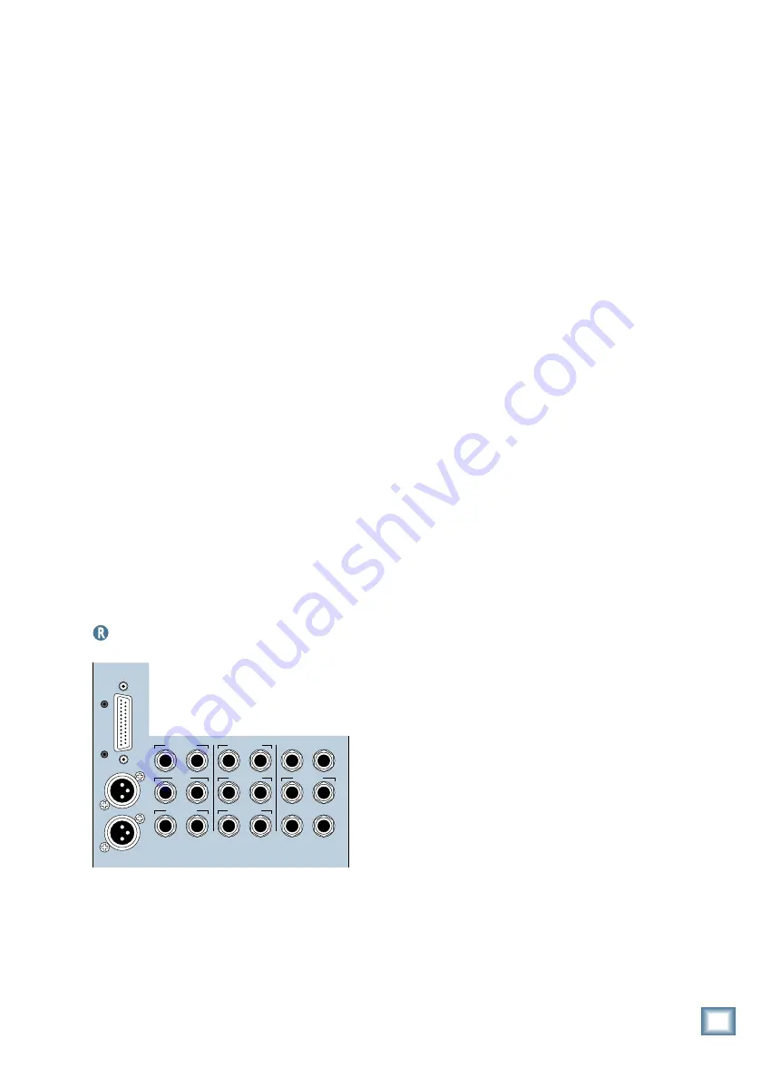
Master Input/Output Section
The Master Outputs are fed from the Master
L-R fader on the console surface. Other output
connections, including PHONES, STUDIO OUT,
and CR MAIN, and NEAR FIELD are fed from
their respective dedicated buses as indicated
on the console surface.
The BUS OUT 1–8 (SURROUND OUT) con-
nector provides eight balanced analog line-level
outputs on a single 25-pin D-Sub connector.
Any channel (1–48), aux send, or ALT IN can
be assigned to one or more bus outputs, with
the output level controlled by the BUS 1–8
MASTERS (Fader Bank 4). See Chapter 4 in
the Digital 8•Bus Owner’s Manual for the pin-
out diagram for the Bus 1–8 25-pin D-Sub
connector.
The analog XLR L-R MASTER OUTputs are
the main left and right outputs. They provide
balanced analog signals, fed post-DSP, fader,
and DAC. These outputs are driven by the main
L-R bus.
The analog TRS L/R MASTER OUTputs
carry the same signal as the XLR MASTER
OUTputs, and are driven by the L-R bus. They
are balanced analog 1/4" output connectors fed
post-DSP, fader and DAC. These outputs can
drive a balanced or an unbalanced input.
The CR MAIN L-R Outputs and the CR
NEAR FIELD L-R Outputs are pairs of 1/4"
TRS stereo line-level outputs for sending sig-
nals to control room speakers. They are
balanced analog signals fed post-DSP, fader
and DAC. The signals at these outputs are the
same, but with independent level control, and
are determined by the Control Room Source se-
lection. These outputs can drive a balanced or
an unbalanced input.
The PHONES 1 and 2 Outputs are unbal-
anced 1/4" TRS jacks for connecting stereo
headphones. These outputs are designed to
drive virtually all stereo headphones. The sig-
nal at these outputs is determined by the
PHONES/CUE MIX 1 and 2 source selection.
Adjust the Cue Mix LEVEL control to compen-
sate for headphones with exceptionally high or
low impedances.
The STUDIO L-R OUTputs are two 1/4"
TRS stereo line-level outputs for sending signals
to the studio. They are balanced analog stereo-
paired outputs fed post-DSP, fader and DAC.
The signal at these outputs is determined by the
Control Room Source selection. These outputs
can drive a balanced or an unbalanced input.
The PUNCH I/O jack is a remote switch con-
nection for activating the master record
function. Use a normally-open switch.
The TALKBACK jack is a remote switch
connection for engaging the talkback function.
It duplicates the Talkback switch in the Control
Room Section. Use a normally-open switch.
The 2 TRACK A, B, and C L-R Inputs are
balanced 1/4" TRS jacks for connecting line-
level input signals from a 2-track recorder. The
separate left/right pairs feed the 2 TRACK A,
B, and C buses in the control room monitoring
section. These inputs can accept balanced and
unbalanced signals.
TALKBACK
PHONES 2
PUNCH I/O
PHONES 1
2 TRACK IN A
MASTER OUT
2 TRACK IN B
STUDIO OUT
2 TRACK IN C
MASTER OUT
L R
L
R
CR
MAIN
BUS OUT 1-8
&
SURROUND OUT
CR
NEAR FIELD
L R
L R
L R
L R
L R
L R
Digital 8•Bus Overview


