Q u i c k S t a r t G u i d e
7
The Basics
down to one of the Bus 1–8 Masters (Fader
Bank 4), and assign the Bus Master to any one
(for a mono mix) or two (for a stereo mix) of
the 24 Tape Outputs.
As you bounce the tracks down, you’ll
monitor the previously recorded tracks through
the monitoring half of the console.
Of course, overdubbing is simply recording
while monitoring both the live source and pre-
recorded tracks.
Mixdown
Mixing down is an art unto itself, but the
Digital 8•Bus gives you the tools to make the
job easier so you can concentrate more on the
art and less on the mechanics. Since the
Digital 8•Bus is fully automated, you can go
through a step-by-step process of adjusting
levels, pans, EQ, and effects. The console
remembers every move you make and plays
them back each time you make a pass, while
you add your creative touch to each and every
track. When you’re done, hit PLAY, sit back
and watch the console perform the complex
tasks you’ve programmed it to do, resulting in
a perfect mix to two-track (or multitrack for
surround-sound applications).
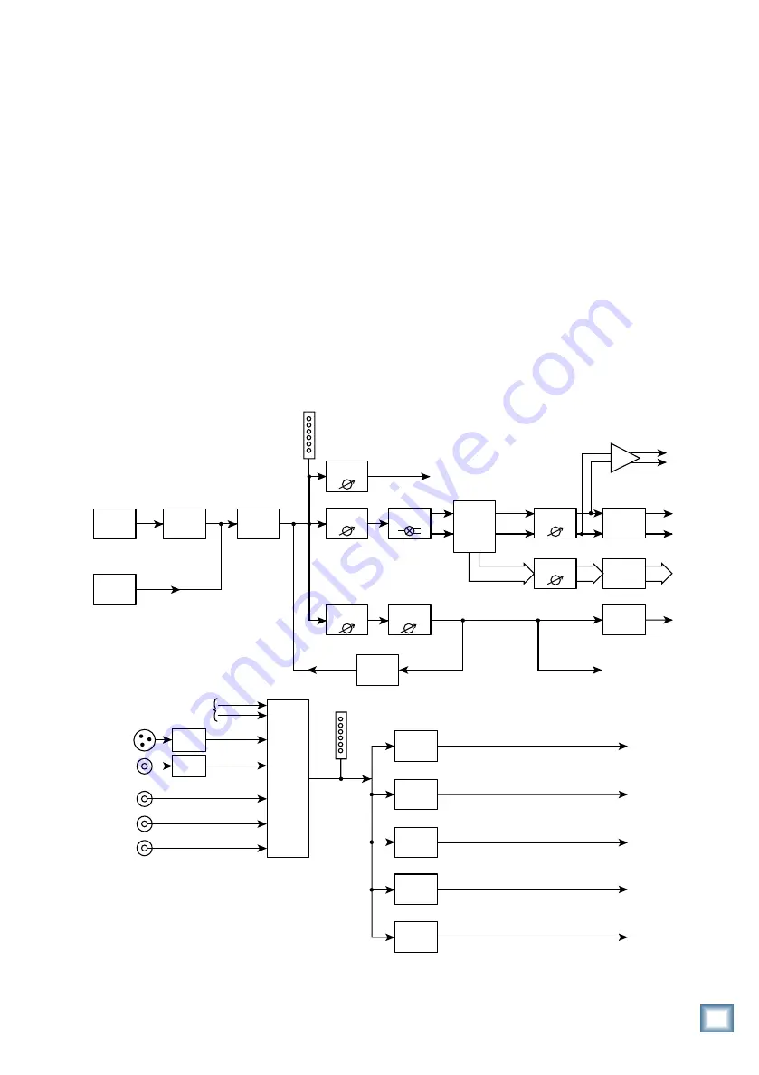
Signal-Flow Diagram
There is a detailed block diagram in the
Digital 8•Bus Owner’s Manual that shows all
the signal flow and computer-controlled logic
within the console. But since this is a Quick
Start Guide, we thought it might be helpful to
have a simpler signal-flow diagram here that
shows the basic signal flow at a glance so you
don’t have to plod through the detailed drawing.
Analog
Inputs
CH 1-48
Optional
Digital Tape
Input
Level to
Tape
To Tape Outputs
L
R
Channel
Fader
Aux Send
Level
Channel
Pan
Bus Master
Bus 1-8
Master L/R
Fader
Digital to
Analog
Converter
Digital to
Analog
Converter
Digital to
Analog
Converter
Main
Out
Bus 1-8
Outputs
Aux
Sends
Lake Sammamish
6 miles
AES/EBU Out
S/PDIF Out
CR
Nearfield
Out
CR
Main
Out
Studio
Out
Bus
Assign
Master Aux
Send Level
Internal
FX
FX
Returns
DAC
From
L/R Out
Main L/R
Meter
Channel
Meter
Tracking/Routing
Monitoring
S/PDIF
AES/EBU
2 TRK A
2 TRK B
2 TRK C
Analog to
Digital
Converter
Control
Room
Select
DSP
Studio
Level
Main
Speaker
Level
Near Field
Speaker
Level
Phones 1
Out
Cue Mix 1
Level
Phones 2
Out
Cue Mix 2
Level
DAC
Figure 6. Simplified Signal-Flow Diagram


