


LION I/O Modules
▪
System Planning
23
4.5
System Architecture
Different system architectures can be realized with the LION product family.
Following points are important to realize a system:
▪ The SIL2 bus coupler is the master of the LION system, the SIL0 I/O modules
are slaves.
▪ Max. 3 lines are possible.
▪ The maximum distance between two lines should be no longer than 10 m.
▪ The first component of every line must be a SIL2 power supply. Other SIL2
power supplies can follow.
▪ The second component of the first line must be the SIL2 bus coupler.
▪ If the system consist of different lines, the last component of the line is a SIL0
line coupler and in the following line the second component must be also a
SIL0 line coupler.
▪ It is possible to connect max. 32 SIL0/SIL2 I/O modules to the SIL2 bus
coupler.
▪ It is not allowed to create a line which is longer than 2 m.
▪ SIL0 (non safe) and SIL2 (safe) I/O modules can be combined in the system.
▪ The I/O modules are the smallest exchangeable unit in the system.
Different system architectures can be found below:
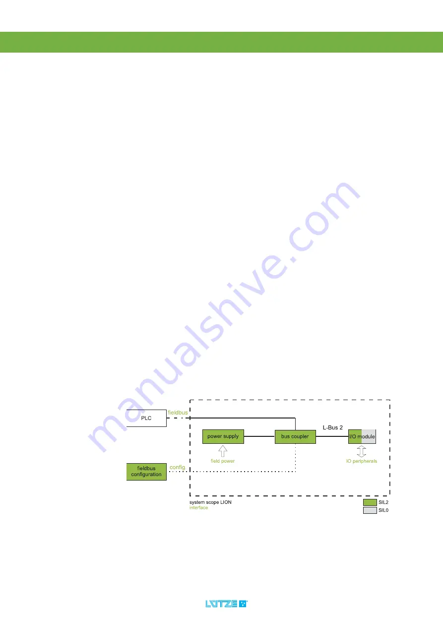
4.5.1
Smallest System
The smallest system contains:
1. one SIL2 power supply,
2. one SIL2 bus coupler and
3. one SIL0/SIL2 I/O module.
All components are in one line.
Fig. 12: System Architecture – Smallest System


