


Digital I/O Modules
▪
Digital Inputs
23
10.2.4
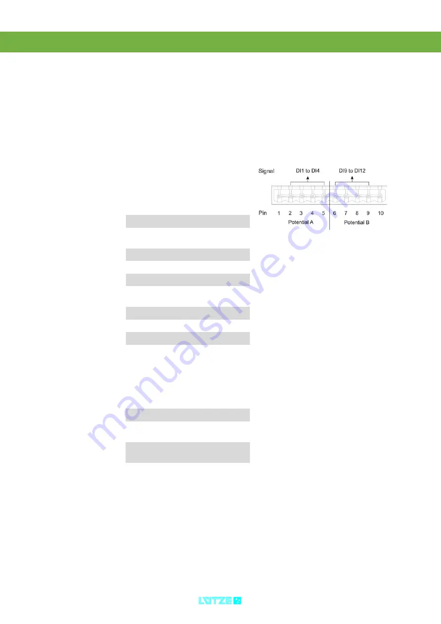
Connecting the Digital Inputs
Connect the digital inputs via the cage clamps X1 and X2. Follow these steps:
1. Switch off the power.
2. Connect the inputs regarding the pin
assignment and the signals.
Digitale Inputs 24, 72 and 110 V
(2 Potentials)
Coding
Cage Clamp X1
Pin
Signal
Description
1
GND
A
0 V - Potential A
2
DI1
Input 1
(1. Byte LSB)
3
DI 2
Input 2
4
DI 3
Input 3
5
DI 4
Input 4
6
DI 9
Input 9
(2nd Byte LSB)
7
DI10
Input 10
8
DI11
Input 11
9
DI12
Input 12
10
GND
B
0 V - Potential B
Module
Plug
Connectors
Cage Clamp
24 V
Pin 2
Pin 3 and 4
72 V
Pin 4 and 7
Pin 2, 3, 5
and 6
110 V
Pin 4 and 6
Pin 2, 3, 5
and 7
Summary of Contents for 746400
Page 1: ...Operation Instructions DIOLINE20 Digital I O Modules Version 4 50...
Page 30: ...Digital I O Modules Digital Inputs 26 10 2 5 2 Block Diagram 2x8 Digital Inputs 72 V...
Page 31: ...Digital I O Modules Digital Inputs 27 10 2 5 3 Block Diagram 2x8 Digital Inputs 110 V...
Page 39: ...Digital I O Modules Digital Inputs 35 10 3 5 2 Block Diagram 4x4 Digital Inputs 72 V...
Page 80: ...Digital I O Modules Relay Outputs 76 13 3 5 Operation 13 3 5 1 Block Diagram Relay Outputs...
Page 81: ...77 14 Spacer 14 1 Characteristics Spacer for project planning Does not have any cage clamps...
Page 89: ...by L tze Transportation GmbH Weinstadt Germany Technical changes reserved...