


Digital I/O Modules
▪
Initial Operation – Hardware
15
9.2
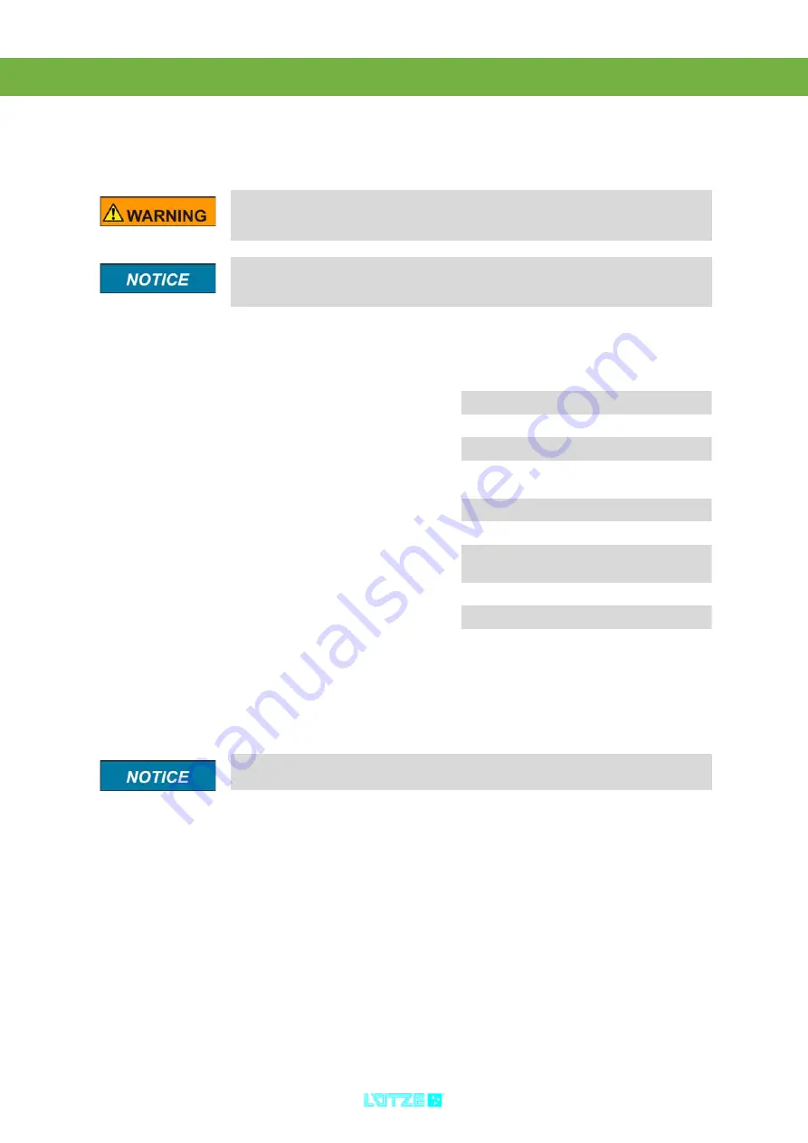
L-Bus – Interface
The L-Bus interface is for coupling the local DIOLINE20 I/O modules. The L-Bus,
(Lütze-Bus) is a special fieldbus invented by company Lütze.
Switch off the power when connecting or disconnecting the I/O modules.
If not observe, the whole system can be damaged. Hot Plugging is not supported
by the system.
Connect max 10 I/O modules over the L-Bus interface.
Mind the current
consumption of the single modules. In the appendix
the according
values are listed. A total current of max 1 A is possible on the L-Bus.
1. Switch off the power.
Pin
Signal
Description
1
24 V
Supply Voltage
2
24 V
Supply Voltage
3
GND
0 V Potential
4
/L_BUS_
RESET
Module Reset
5
BUS_END
Identifier Bus End
6
OUT_OK
Data Confirmation
7
MDIN
Serial Input Data
Master
8
SCK
Clock
9
SDOUT
Sending Serial Data
10
GND
0 V Potential
A change of the pin assignment is not possible, because of the
predetermined connectors.
Summary of Contents for 746400
Page 1: ...Operation Instructions DIOLINE20 Digital I O Modules Version 4 50...
Page 30: ...Digital I O Modules Digital Inputs 26 10 2 5 2 Block Diagram 2x8 Digital Inputs 72 V...
Page 31: ...Digital I O Modules Digital Inputs 27 10 2 5 3 Block Diagram 2x8 Digital Inputs 110 V...
Page 39: ...Digital I O Modules Digital Inputs 35 10 3 5 2 Block Diagram 4x4 Digital Inputs 72 V...
Page 80: ...Digital I O Modules Relay Outputs 76 13 3 5 Operation 13 3 5 1 Block Diagram Relay Outputs...
Page 81: ...77 14 Spacer 14 1 Characteristics Spacer for project planning Does not have any cage clamps...
Page 89: ...by L tze Transportation GmbH Weinstadt Germany Technical changes reserved...