Lütze 746400 Operation Instructions Manual Download Page 22

Digital I/O Modules 

 Digital Inputs

18

10.2

2x8 Digital Inputs DC 24, 72, 110 V  
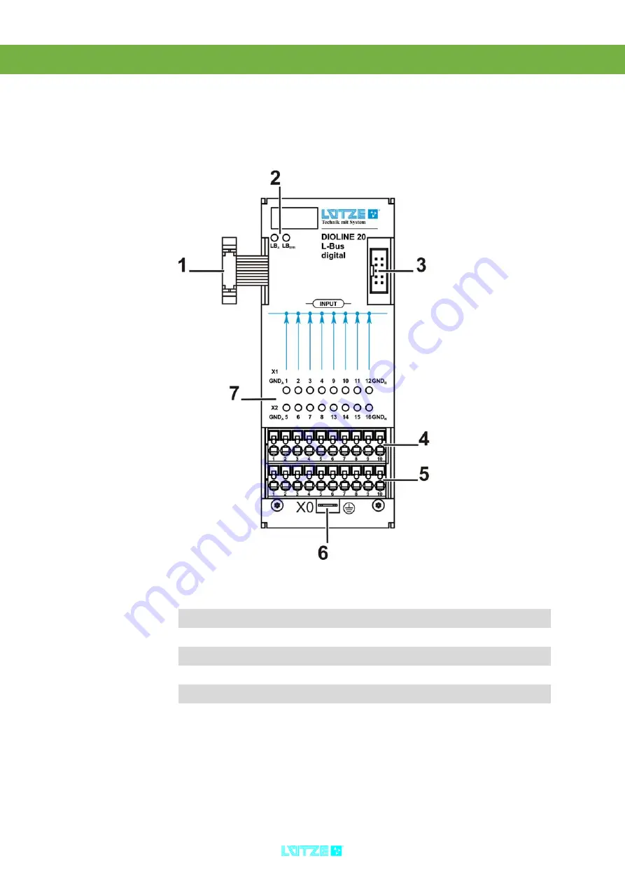
10.2.1

Product Assembly

1

L-Bus Interface – incoming

2

LED Diagnosis Display – L-Bus

3

L-Bus Interface – outgoing

4

Connector Digital Inputs

5

Connector Digital Inputs

6

Neutral Conductor – Mounting Tab

7

LED Diagnosis Display – Digital Inputs

Summary of Contents for 746400

Page 1: ...Operation Instructions DIOLINE20 Digital I O Modules Version 4 50...

Page 2: ...L tze Transportation GmbH Bruckwiesenstra e 17 19 D 71384 Weinstadt Tel 49 0 7151 6053 545 Fax 49 0 7151 6053 6454 Sales Transportation luetze de www luetze transportation de...

Page 3: ...Transport and Storing 9 6 Scope of Delivery 10 7 General Technical Data 11 8 Mounting 13 8 1 Mounting Options 13 9 Initial Operation Hardware 14 9 1 Power Supply 14 9 2 L Bus Interface 15 10 Digital...

Page 4: ...ata 56 11 5 4Connecting the Digital Outputs 58 11 5 5Diagnosis 59 11 5 6Operation 60 12 Digital Combination 62 12 1 Characteristics 62 12 2 2x4 2x4 Digital Combi Module DC 24 V 63 12 2 1Product Assemb...

Page 5: ...I O Modules It contains important information about the handling and safety To avoid hazardous situations read the manual before installing the product and using it Store the manual at a handy place I...

Page 6: ...by titleholder 2 3 Disclaim of Liability The manual was written under consideration of the applied standards regulations and the current state of technology The content is verified of accuracy Discrep...

Page 7: ...l I O Modules General Information 3 2 4 Related Documents The digital I O modules are always operated with different PLCs and buscoupler Read the manual of the PLC or buscoupler before using the I O m...

Page 8: ...cts and systems Regarding the employees different qualification levels are differentiated 3 4 Operating Employees Trained Employees The employee was trained by the employer on the task and possible ha...

Page 9: ...se static electrification can destroy parts of the buscoupler which can cause a malfunction of the whole product Follow the instructions and regulations of the employer Reconstructions and modificatio...

Page 10: ...Type 8 digital Inputs 8 digital Outputs 16 digital Inputs 16 digital Outputs 8 digital Inputs 8 digital Outputs 4 analog Inputs 4 analog Outputs 4 analog Inputs multiplexed 4analog Outputs multiplexe...

Page 11: ...cal I O extension modules on the controller The extension modules are connected over the L Bus The graphic shows the DIOLINE product after their intelligence The first module is the most intelligent o...

Page 12: ...Digital I O Modules Product Overview 8 4 3 Field of Application The DIOLINE20 I O Modules can be connected to buscoupler or PLCs...

Page 13: ...oduct in a dry room between 40 and 85 C Make sure that the I O modules are safely packaged for transporting to absorbe possible crushes Dust can destroy electronic components The circuit boards of the...

Page 14: ...Digital I O Modules Scope of Delivery 10 6 Scope of Delivery DIOLINE20 I O Module Plug in Connector Instruction Leaflet...

Page 15: ...ons WxHxD 57 0x141 5x48 0 mm Housing aluminum Mounting top hat rail Electronic Module Supply Voltage Supply DC 16 8 30 V Ripple max 10 Enviromental Condition Operating Temperature 40 C to 70 C 85 C fo...

Page 16: ...Data 12 Standards EN 50155 Electronic equipment on railway vehicles EN 50121 Electromagnetic compability EN 50124 Insulation coordination EN 61373 Vibration and shocks For detailled standard informati...

Page 17: ...t People can be injured by electric current and the product can be damaged Deenergize the system before mounting Mount the product with a distance of 5 mm minimum to other products to provide good air...

Page 18: ...also find information about the pin assignments 9 1 Power Supply The built in microcontroller of the digital I O module is feeded by the L Bus interface The power supply has to be connected over the...

Page 19: ...ax 10 I O modules over the L Bus interface Mind the current consumption of the single modules In the appendix Seite 84 the according values are listed A total current of max 1 A is possible on the L B...

Page 20: ...ial Operation Hardware 16 2 Connect the DIOLINE 20 I O modules via the L Bus Interface 3 Switch on the power 4 The LB LED is green The devices are ready for operation Fig 2 L Bus Master Fig 3 MVB Busc...

Page 21: ...the inputs and the system bus And also between the inputs of the different groups Antiparallel Diode Avoids the damage of entry levels at the confusing of poles of the input and the ground Suppressor...

Page 22: ...Inputs DC 24 72 110 V 10 2 1 Product Assembly 1 L Bus Interface incoming 2 LED Diagnosis Display L Bus 3 L Bus Interface outgoing 4 Connector Digital Inputs 5 Connector Digital Inputs 6 Neutral Conduc...

Page 23: ...Digital I O Modules Digital Inputs 19 10 2 2 LED Display 10 2 2 1 LEDs L Bus 10 2 2 2 LEDs Input Signals LED Color Status LBA green active LBERR red Error LED Color Status 1 16 yellow Sensor active...

Page 24: ...puts and electronic AC 1 5 kV input potentials against each other Input Voltage 0 Signal DC 0 6 V 1 Signal DC 12 5 30 V Input Current 0 Signal 0 mA 1 Signal at DC 24 V min 25 mA for 7 ms when powering...

Page 25: ...ectronic AC 1 5 kV input potentials against each other Input Voltage 0 Signal 0 18 V DC 1 Signal 36 90 V DC Input Current 0 Signal 0 mA 1 Signal at DC 72 V min 8 mA for 7 ms when powering up sloping t...

Page 26: ...potential against each other Input Voltage 0 Signal DC 0 27 5 V 1 Signal DC 55 137 5 V Input Current 0 Signal 0 mA 1 Signal at DC 110 V min 5 mA for 7 ms when powering up sloping to min 1 2 mA 1 Sign...

Page 27: ...and the signals Digitale Inputs 24 72 and 110 V 2 Potentials Coding Cage Clamp X1 Pin Signal Description 1 GNDA 0 V Potential A 2 DI1 Input 1 1 Byte LSB 3 DI 2 Input 2 4 DI 3 Input 3 5 DI 4 Input 4 6...

Page 28: ...l A 2 DI 5 Input 5 3 DI 6 Input 6 4 DI 7 Input 7 5 DI 8 Input 8 1st Byte MSB 6 DI13 Input 13 7 DI14 Input 14 8 DI15 Input 15 9 DI16 Input 16 2nd Byte MSB 10 GNDB 0 V Potential B Modul Plug Connectors...

Page 29: ...Digital I O Modules Digital Inputs 25 10 2 5 Operation 10 2 5 1 Block Diagram 2x8 Digital Inputs 24 V...

Page 30: ...Digital I O Modules Digital Inputs 26 10 2 5 2 Block Diagram 2x8 Digital Inputs 72 V...

Page 31: ...Digital I O Modules Digital Inputs 27 10 2 5 3 Block Diagram 2x8 Digital Inputs 110 V...

Page 32: ...Inputs DC 24 and 72 V 10 3 1 Product Assembly 1 L Bus Interface outgoing 2 LED Diagnosis Display L Bus 3 L Bus Interface incoming 4 Connector Digital Inputs 5 Connector Digital Inputs 6 Neutral Conduc...

Page 33: ...Digital I O Modules Digital Inputs 29 10 3 2 LED Display 10 3 2 1 LEDs L Bus 10 3 2 2 LEDs Input Signals LED Color Status LBA green active LBERR red Error LED Color Status 1 16 yellow Sensor active...

Page 34: ...inputs and electronic AC 1 5 kV between potential A B C and D Input Voltage 0 Signal DC 0 6 V 1 Signal DC 12 5 30 V Input Current 0 Signal 0 mA 1 Signal at DC 24 V min 25 mA for 7 ms when powering up...

Page 35: ...electronic AC 1 5 kV between potential A B C and D Input Voltage 0 Signal DC 0 18 V 1 Signal DC 36 90 V Input Current 0 Signal 0 mA 1 Signal at DC 72 V min 8 mA for 7 ms when powering up sloping to m...

Page 36: ...the pin assignment and the signals Digital Inputs 24 and 72 V 4 Potentials Coding Cage Clamp X1 Pin Signal Description 1 GNDA 0 V Potential A 2 DI1 Input 1 1st Byte LSB 3 DI 2 Input 2 4 DI 3 Input 3...

Page 37: ...GNDA 0 V Potential A 2 DI 5 Input 5 3 DI 6 Input 6 4 DI 7 Input 7 5 DI 8 Input 8 1st Byte MSB 6 DI13 Input 13 7 DI14 Input 14 8 DI15 Input 15 9 DI16 Input 16 2nd Byte MSB 10 GNDB 0 V Potential B Modu...

Page 38: ...Digital I O Modules Digital Inputs 34 10 3 5 Operation 10 3 5 1 BLock Diagram 4x4 Digital Inputs 24 V...

Page 39: ...Digital I O Modules Digital Inputs 35 10 3 5 2 Block Diagram 4x4 Digital Inputs 72 V...

Page 40: ...of the different groups Suppressor Diode Surge protection Short Circuit Proofed Temperatur sensor Avoids overcharging of the outputs Schottky Diode only redundant outputs Module 2x8 DC 24 V redundant...

Page 41: ...igital Outputs 24 V DC redundancy capable 11 2 1 Product Assembly 1 L Bus Interface incoming 2 LED Diagnosis Display L Bus 3 L Bus Interface outgoing 4 LED Diagnosis Display Digital Inputs 5 Connector...

Page 42: ...ts 38 11 2 2 LED Display 11 2 2 1 LEDs L Bus 11 2 2 2 LEDs Output Signals LED Color Status LBA green active LBERR red Error LED Color Status 1 16 yellow Sensor active USA green red Supply OK Overload...

Page 43: ...nt Enviromental Temperature 50 C 2 A per channel 8 A per group A B Enviromental Temperature 50 C 1 25 A per channel 5 A per group A B Idle Current Consumption 6 5 mA per group Limit Threshold thermic...

Page 44: ...nviromental temperature 50 C 2 A per channel 8 A per group A B Enviromental temperature 50 C 1 25 A per channel 5 A per group A B Closed Current 6 5 mA per group Limit Threshold thermic 10 Hz at 50 ED...

Page 45: ...nd the signals Digital Outputs 24 V redundant compatible All outputs have a redundant diode Coding Cage Clamp X1 Pin Signal Description 1 USA 24 V DC Potential A 2 DO 1 Output 1 1st Byte LSB 3 DO 2 Ou...

Page 46: ...DA 0 V Potential A 2 DO 5 Output 5 3 DO 6 Output 6 4 DO 7 Output 7 5 DO 8 Output 8 1st Byte MSB 6 DO 13 Output 13 7 DO 14 Output 14 8 DO 15 Output 15 9 DO 16 Output 16 2nd Byte MSB 10 GNDB 0 V Potenti...

Page 47: ...Digital I O Modules Digital Outputs 43 11 2 5 Operation 11 2 5 1 Block Diagram 2x8 Digital Outputs 24 V...

Page 48: ...Digital I O Modules Digital Outputs 44 11 2 5 2 Block Diagram 2x8 Digital Outputs 24 V redundancy capable...

Page 49: ...gital Outputs DC 24 V with Diagnosis redundancy capable 11 3 1 Product Assembly 1 L Bus Interface incoming 2 LED Diagnosis Display L Bus 3 L Bus Interface outgoing 4 LED Diagnosis Display Digital Outp...

Page 50: ...1 LEDs L Bus 11 3 2 2 LEDs Input Signals LED Color Status LBA green active LBERR red Error LED Color Status 1 8 yellow Actor active USA green red Supply OK Overload USB green red Supply OK Overload U...

Page 51: ...ential group max 16 A per module At a max load of 4 A on at least one channel following fragmentation results max 12 A per module Output 1 2 3 4 5 6 7 8 Max load 0A 2A 4A 0A 0A 4A 2A 0A Safety Functio...

Page 52: ...ups Output Current max 2 A per channel max 3 A per potential group max 12 A per module Power consumption max 5 mA per group Safety Function inverse polarity protection short circuit proof abnormal tem...

Page 53: ...ment and the signals Digital Outputs 24 V capable of redundancy Diagnosis Coding Cage Clamp X1 Pin Signal Description 1 USA DC 24 V Potential A 2 DO 1 Output1 1st Byte LSB 3 NC Not connected 4 USB DC...

Page 54: ...DA 0 V Potential A 2 DO 2 Output 2 3 NC Not connected 4 GNDB 0 V Potential B 5 DO 4 Output 4 6 DO 6 Output 6 7 GNDC 0 V Potential C 8 NC Not connected 9 DO 8 Output 8 1st Byte MSB 10 GNDD 0 V Potentia...

Page 55: ...Bit 5 Bit 4 Bit 3 Bit 2 Bit 1 Bit 0 Switching Status actual Output Channel DO 8 Switching Status actual Output Channel DO 7 Switching Status actual Output Channel DO 6 Switching Status actual Output C...

Page 56: ...Digital I O Modules Digital Outputs 52 11 3 6 Operation 11 3 6 1 Block Diagram 4x2 Digital Outputs 24 V...

Page 57: ...Digital I O Modules Digital Outputs 53 11 3 6 2 Block Diagram 4x2 Digitale Outputs 24 V redundancy capable...

Page 58: ...tal Outputs DC 110 V redundancy capable 11 4 1 Product Assembly 1 L Bus Interface incoming 2 LED Diagnosis Display L Bus 3 L Bus Interface outgoing 4 LED Diagnosis Display Digital Outputs 5 Connector...

Page 59: ...Digital I O Modules Digital Outputs 55 11 5 LED Display 11 5 1 LEDs L Bus 11 5 2 LEDs Output Signals LED Color Status LBA green active LBERR red Error LED Color Status 1 6 yellow Output active...

Page 60: ...tputs and electronic AC 1 5 kV between the outputgroups Output Voltage DC 24 110 V Output Current max 2 A per channel Safety Function inverse polarity protection short circuit proof abnormal temperatu...

Page 61: ...sulation Potential Voltage AC 1 5 kV outputs and electronic AC 1 5 kV between the output groups Output Current 0 6 A per channel Safety Function inverse polarity protection short circuit proof abnorma...

Page 62: ...le Diagnosis Cage Clamp X1 and X2 Pin Signal Description 1 USA DC 110 V Potential A 2 DO 1 Output 1 3 DO 2 Output 2 4 USB 110 V DC Potential B 5 DO 3 Output 3 6 DO 4 Output 4 7 USC 110 V DC Potential...

Page 63: ...uit or overtemperature at the output channel DOx Byte 1 Read back Byte Bit 7 Bit 6 Bit 5 Bit 4 Bit 3 Bit 2 Bit 1 Bit 0 0 0 Switching Status actual Output Channel DO 6 Switching Status actual Output Ch...

Page 64: ...Digital I O Modules Digital Outputs 60 11 5 6 Operation 11 5 6 1 Block Diagram 6 Digital Outputs 110 V...

Page 65: ...Digital I O Modules Digital Outputs 61 11 5 6 2 Block Diagram 6 Digital Outputs 110 V redundancy capable...

Page 66: ...12 Digital Combination 12 1 Characteristics Module with In and Outputs Same characteristics as the corresponding in and output modules The four inputs and outputs inside a group have the same potenti...

Page 67: ...ital Combi Module DC 24 V 12 2 1 Product Assembly 1 L Bus Interface incoming 2 LED Diagnosis Display L Bus 3 L Bus Interface outgoing 4 Connector Digital Inputs 5 Connector Digital Inputs 6 Neutral Co...

Page 68: ...on 64 12 2 2 LED Display 12 2 2 1 LEDs L Bus 12 2 2 2 LEDs Input Signal LED Color Status LBA green active LBERR red Error LED Color Status 1 16 yellow Sensor Actor active USA green red Supply OK Overl...

Page 69: ...nom 10 mA Potential Insulation Voltage Insulation AC 1 5 kV outputs and electronic AC 1 5 kV potential A to B Input Voltage 0 Signal DC 0 6 V 1 Signal DC 12 5 30 V Input Current 0 Signal 0 mA 1 Signa...

Page 70: ...shold thermic 10 Hz at 50 ED Safety Function inverse polarity protection short circuit proof abnormal temperature protection Channel Type N MOS FET Standby Current 3 0 mA per group External Fuse B10 D...

Page 71: ...Connect the outputs and inputs regarding the pinassignment and the signals Digital Combi Module 24 V Coding Cage Clamp X1 Pin Signal Description 1 USA 24 V DC Potential A 2 DO 1 Output 1 1st Byte LSB...

Page 72: ...p X2 Pin Signal Description 1 GNDA 0 V Potential A 2 DI 1 Input 1 LSB 3 DI 2 Input 2 4 DI 3 Input 3 5 DI 4 Input 4 6 DI 5 Input 5 7 DI 6 Input 6 8 DI 7 Input 7 9 DI 8 Input 8 MSB 10 GNDB 0 V Potential...

Page 73: ...Digital I O Modules Digital Combination 69 12 2 5 Operation 12 2 5 1 Block Diagram 2x4 2x4 DC 24 V Digital Combi Module...

Page 74: ...6 switching cycles relay data Electrical At 0 2 A 30 V DC a resitive load and an enviromental temperature of 85 C the electrical lifetime of the relay module is more than 30000 switching cycles relay...

Page 75: ...ay Outputs 13 3 1 Product Assembly 1 L Bus Interface incoming 2 LED Diagnosis Display L Bus 3 L Bus Interface outgoing 4 LED Diagnosis Display Digital Outputs 5 Connector Digital Outputs 6 Connector D...

Page 76: ...Digital I O Modules Relay Outputs 72 13 3 2 LED Display 13 3 2 1 LEDs L Bus 13 3 2 2 LEDs Output Signal LED Color Status LBA green active LBERR red Error LED Color Status R1 R6 yellow Aktor active...

Page 77: ...inst channel Switch On Delay with CAN processing 13 28 ms Switch Off Delay with CAN processing 11 15 ms Output Current DC 0 4 A at DC 150 V Ohm resistive Load DC 6 A at DC 30 V Ohm resistive Load AC 6...

Page 78: ...uts regarding the pin assignment and the signals Relay Output Coding Cage Clamp X1 Pin Signal Beschreibung 1 11 Relay 1 C Contact 2 14 Relay 1 NO Contact 3 12 Relay 1 NC Contact 4 31 Relay 3 C Contact...

Page 79: ...21 Relay 2 C Contact 2 24 Relay 2 NO ontact 3 22 Relay 2 NC ontact 4 41 Relay 4 C Contact 5 44 Relay 4 NO Contact 6 42 Relay 4 NC Contact 7 61 Relay 6 C Contact 8 64 Relay 6 NO Contact 9 62 Relay 6 N...

Page 80: ...Digital I O Modules Relay Outputs 76 13 3 5 Operation 13 3 5 1 Block Diagram Relay Outputs...

Page 81: ...77 14 Spacer 14 1 Characteristics Spacer for project planning Does not have any cage clamps...

Page 82: ...Digital I O Modules Spacer 78 14 2 Product Assembly 1 L Bus Interface incoming 2 LED Diagnosis Display L Bus 3 L Bus Interface outgoing 4 Neutral Conductor Mounting Tab...

Page 83: ...Digital I O Modules Spacer 79 14 2 1 LED Display 14 2 1 1 LEDs L Bus LED Color Status LBA green active LBERR red Error...

Page 84: ...sche Daten Supply Ripple max 10 Current Consumption at DC 24 V nom 10 mA Threshold thermic 10 Hz at 50 ED Spacer Data Width in the Process Image 1 Byte inputs content 0x00 Module Status Flag The modul...

Page 85: ...Digital I O Modules Demounting 81 15 Demounting 1 Push the module up 2 Pull the module from the top hat rail 3 Push the module down and take the module off the rail...

Page 86: ...ze Transportation GmbH from the responsibilities of 10 passage 2 ElektroG Take back obligation of the manufacturer and any third party in this content If you have handled the device to a commercial th...

Page 87: ...If you have any further questions regarding the product or our repairing service please contact us L tze Transportation GmbH Bruckwiesenstra e17 19 71384 Weinstadt Tel 49 0 7151 6053 545 Fax 49 0 7171...

Page 88: ...0 Identifier Type I O Range Length Bytes ID hex 8 Digital Inputs 8DI 1 0 F2 8 Digital Outputs 8DO 0 1 F1 16 Digital Inputs 16DI 2 0 E0 16 Digital Outputs 16DO 0 2 E1 8 Digital Inputs 8 Digital Outputs...

Page 89: ...by L tze Transportation GmbH Weinstadt Germany Technical changes reserved...

Reviews: