


Digital I/O Modules
▪
Initial Operation – Hardware
14
9
Initial Operation – Hardware
To connect the modules correctly read the chapter of the required module. In the
chapters you will also find information about the pin assignments.
9.1
Power Supply
The built in microcontroller of the digital I/O module is feeded by the L-Bus
interface. The power supply has to be connected over the cage clamps of the
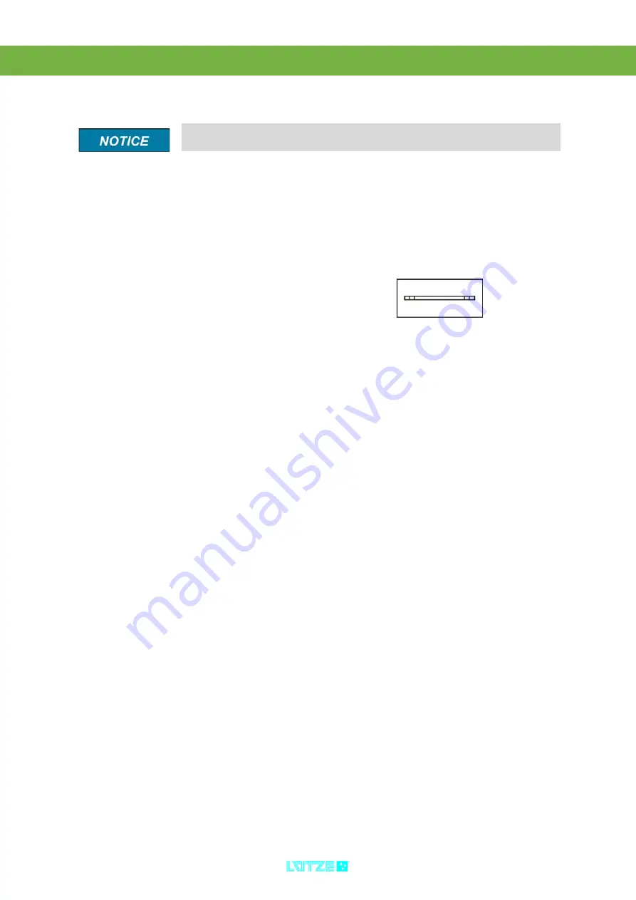
modules. Read the required chapter. To ground the module connect the mounting
tab X0.
Fig. 1: Mounting Tab X0
The initial operation has to be done by electricians.
Summary of Contents for 746400
Page 1: ...Operation Instructions DIOLINE20 Digital I O Modules Version 4 50...
Page 30: ...Digital I O Modules Digital Inputs 26 10 2 5 2 Block Diagram 2x8 Digital Inputs 72 V...
Page 31: ...Digital I O Modules Digital Inputs 27 10 2 5 3 Block Diagram 2x8 Digital Inputs 110 V...
Page 39: ...Digital I O Modules Digital Inputs 35 10 3 5 2 Block Diagram 4x4 Digital Inputs 72 V...
Page 80: ...Digital I O Modules Relay Outputs 76 13 3 5 Operation 13 3 5 1 Block Diagram Relay Outputs...
Page 81: ...77 14 Spacer 14 1 Characteristics Spacer for project planning Does not have any cage clamps...
Page 89: ...by L tze Transportation GmbH Weinstadt Germany Technical changes reserved...