Installing the CBX 500 Switch
Connecting External Clock Inputs and Outputs
Beta Draft Confidential
4-18
4/5/03
CBX 500 Multiservice WAN Switch Hardware Installation Guide
Connecting External T1 Clock Source Inputs/Outputs
To connect an external T1 clock source input or output:
1. Remove the protective cover from the wire-wrap pins.
2. Using a solid 26 AWG wire, strip the end of the wire approximately 1 to 1-1/2
inches.
3. Insert the stripped end of the wire into a wire-wrap gun for a .045 square post.
4. Use the wire-wrap gun to install the wire onto the wire-wrap pins.
5. Reinstall the protective cover onto the wire-wrap pins.
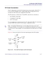
To connect an external E1 clock-source input or clock output, connect a 75-ohm cable
with a BNC connector to the appropriate BNC port on the SPA module.

