


Chapter 5 Communication Program
5 - 9
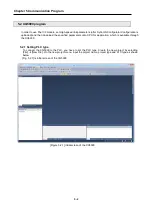
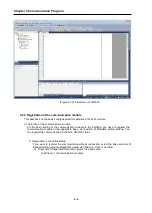
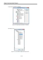
(3) Screen after “SyCon Upload”
[Figures 5.2.11] Screen after SyCon uploaded
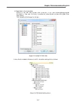
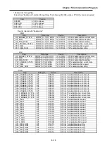
(4) High-speed link parameter settings
Classification
Details
Master
Station No.
Display the Master station no.
Station No. *1
Setting range for the slave : 0 ~ 126
If identical station No. is set, communication will not be normal.
Mode *1
Sending: Transmission the data from master module to slave module.
Receiving: Transmission the data from slave module to master module.
Read area
(Master module
→
Slave module)
XGK
Area to set the start address of device used for Sending.
Setting device : P, M, K, F, T, C, U, Z, L, N, D, R, ZR
XGI
Area to set the start address of device used for Sending.
Setting device : A, M, I, Q, R, W, F, K, L, N, U
Save area
(Slave module
→
Master module)
XGK
Area to set the start address of device used for Receiving.
Setting device : P, M, K, F, T, C, U, Z, L, N, D, R, ZR
XGI
Area to set the start address of device used for Receiving.
Setting device : A, M, I, Q, R, W, F, K, L, N, U
Send data
Receive data
(Byte)
Display input/output points of slave module by the bytes.
- In case of I/O module of 8 bits or less, please set 1 byte.
*1 : Area is not able to set
[Table 5.2.2] High-speed link Block Settings
Summary of Contents for XGL-PMEA
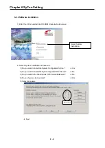
Page 53: ...Chapter 6 SyCon Setting 6 4 5 Configuration Setup Select Next ...
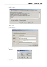
Page 55: ...Chapter 6 SyCon Setting 6 6 3 Setup complete 6 Installed contents 1 Installed file ...
Page 148: ...Chapter 10 Program Example 10 27 Figure 10 2 24 Link Enable High speed link P2P ...
Page 176: ...Chapter 11 Troubleshooting 11 10 11 4 3 XG5000 abnormal connection ...
Page 189: ...Appendix A 8 A 3 Dimensions XGL PMEA B C have same dimensions Unit mm ...