


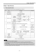


Chapter 2 Specifications
2 - 3
2.3 Structure & Characteristics
2.3.1 Structure of Pnet I/F module
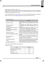
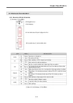
(1) Structure of XGL-PMEA
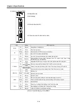
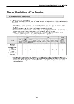
[Table 2.3.1] LED display of XGL-PMEA
LED
Status
LED description
RUN
On
Normal Completion of initialization
Off
Error
Occurrence of error
I/F
Blink
Normal
Normal status of CPU module and interface
Off
Error
Error of CPU module and interface
HS
On
Normal
Service is normal status when High-speed link is enabled
Blink
Stand by
Communication break status between Pnet I/F module and slave when
downloading by Sycon
Off
Error
High-speed link service error occurred when High-speed link is enabled
P-RUN
Blink
Stop
Stop status of communication status between Pnet I/F module and slave
module
On
Run
Run status of Communication between Pnet I/F module and slave
module
STAT
On
Normal
Normal status of High-speed link communication
Off
Error
Abnormal status of Master module
ERR
On
Error
It needs to check the slave module
Off
Normal
Normal status
◀
LED display
◀
Connection area of Sycon Configuration Tool
◀
Connection area of communication cable
◀
Designation area
Summary of Contents for XGL-PMEA
Page 53: ...Chapter 6 SyCon Setting 6 4 5 Configuration Setup Select Next ...
Page 55: ...Chapter 6 SyCon Setting 6 6 3 Setup complete 6 Installed contents 1 Installed file ...
Page 148: ...Chapter 10 Program Example 10 27 Figure 10 2 24 Link Enable High speed link P2P ...
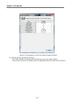
Page 176: ...Chapter 11 Troubleshooting 11 10 11 4 3 XG5000 abnormal connection ...
Page 189: ...Appendix A 8 A 3 Dimensions XGL PMEA B C have same dimensions Unit mm ...