


Chapter 8 High-speed Link
8 - 7
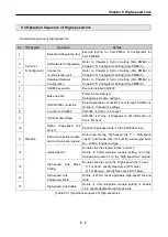
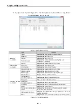
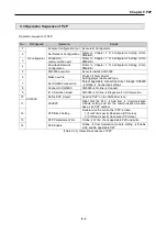
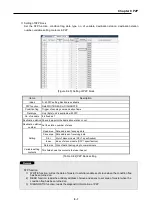
Items
Description
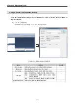
Communication
module settings
Module
type
Select Pnet I/f module
Base No.
Setting of base position installed
Range of Setting: 0 ~ 7 (varying depending on the CPU module)
Slot No.
Setting of slot position installed
Range of Setting: 0 ~ 11
High-
speed link
index
Setting of High-speed link index number
Range of Setting: 1~12
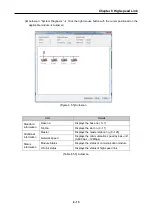
Communication
period settings
Period
type
- Range of setting: 20
㎳
, 50
㎳
, 100
㎳
, 200
㎳
, 500
㎳
, 1s, 5s, 10s
(default is 20
㎳
)
- This applied to Send data
- But Receive data will be processed in every scan end regardless
of communication period.
Output data
setup in
case of
emergency
settings
CPU
error
Latch
Keeps its output status
(But, P device data is cleared)
Clear
Clears all outputs
CPU
stop
Latch
Keeps its output status
(But, P device data is cleared)
Clear
Clears all outputs
[Table 8.4.2] Setting of communication module
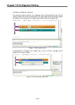
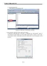
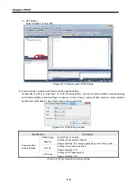
7) Config. Upload
After “Setting of communication module and communication period” is complete, while putting the
mouse cursor on High-speed link window (right screen of XG5000), and select “Online”
“Communication module setting”
“Config. Upload (Dnet, Pnet)” to upload a configuration file.
Summary of Contents for XGL-PMEA
Page 53: ...Chapter 6 SyCon Setting 6 4 5 Configuration Setup Select Next ...
Page 55: ...Chapter 6 SyCon Setting 6 6 3 Setup complete 6 Installed contents 1 Installed file ...
Page 148: ...Chapter 10 Program Example 10 27 Figure 10 2 24 Link Enable High speed link P2P ...
Page 176: ...Chapter 11 Troubleshooting 11 10 11 4 3 XG5000 abnormal connection ...
Page 189: ...Appendix A 8 A 3 Dimensions XGL PMEA B C have same dimensions Unit mm ...