


Chapter 10 Program Example
10 - 38
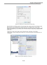
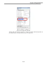
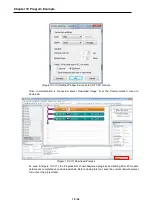
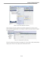
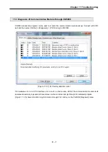
[Figure 10.3.17] Screen of communication module setting
Select the Pnet for module type, position of current master communication module is set the base number
and slot number. Communication cycle is set free from 20ms to 10s (Basic 20ms), It will be a data
transmission cycle between CPU module of PLC and Master communication module. In emergency, output
setting is set suitable to user’s environment. Click ‘OK’ and then ‘Block’ is created below ‘High-speed link 1’,
Double click it.
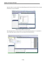
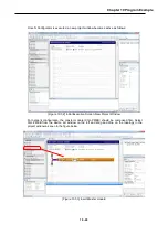
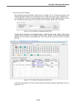
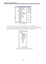
After block is created, click the index of block information frame (right frame). Click [Online]-
[Communication module setting]-[Config. Upload (Dnet, Pnet) and it brought the setting information in N
Configurator
Summary of Contents for XGL-PMEA
Page 53: ...Chapter 6 SyCon Setting 6 4 5 Configuration Setup Select Next ...
Page 55: ...Chapter 6 SyCon Setting 6 6 3 Setup complete 6 Installed contents 1 Installed file ...
Page 148: ...Chapter 10 Program Example 10 27 Figure 10 2 24 Link Enable High speed link P2P ...
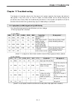
Page 176: ...Chapter 11 Troubleshooting 11 10 11 4 3 XG5000 abnormal connection ...
Page 189: ...Appendix A 8 A 3 Dimensions XGL PMEA B C have same dimensions Unit mm ...