


Chapter 3 Installation and Test Operation
3 - 4
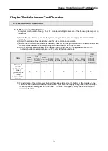
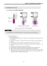
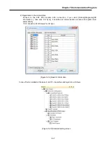
2) Pnet Connector structure and wiring method
(1) Input Line: green line is connected to A1, red line is connected to B1
(2) Output line: green line is connected to A2, red line is connected to B2
(3) Connect shield to clamp of shield
(4) In case of installing the connector at terminal, install the cable at A1, B1
<Connector structure>
<Cable structure>
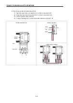
<Cable wiring method>
Summary of Contents for XGL-PMEA
Page 53: ...Chapter 6 SyCon Setting 6 4 5 Configuration Setup Select Next ...
Page 55: ...Chapter 6 SyCon Setting 6 6 3 Setup complete 6 Installed contents 1 Installed file ...
Page 148: ...Chapter 10 Program Example 10 27 Figure 10 2 24 Link Enable High speed link P2P ...
Page 176: ...Chapter 11 Troubleshooting 11 10 11 4 3 XG5000 abnormal connection ...
Page 189: ...Appendix A 8 A 3 Dimensions XGL PMEA B C have same dimensions Unit mm ...