background image

Troubleshooting

23

23.1.1

Going over PoE budget will result in video loss

Our recorders use

Power over Ethernet (PoE)

technology to deliver power to IP cameras and the

same PoE is used to transmit video back to the recorder.

Known as

Maximum Power Consumption

(wattage), each IP camera requires a specific

amount of power to operate and function efficiently. You will find the Max Power Consumption
on the camera's specification sheet in the Download section of the camera's product page.

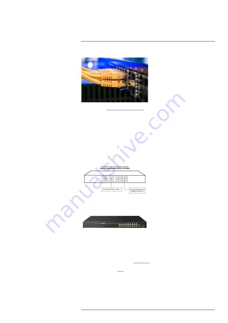
Our Network Video Recorders (NVR) have a total power output or

PoE budget

of between

80

and 220 watts

. When adding additional cameras to your recorder, please ensure that you do not

exceed the PoE budget. If you go over your PoE budget, the system will shut down or drop a
camera as it does not have enough power to supply to the camera, resulting in video loss.

When adding cameras to your recorder, please make sure you are within your wattage allowance.
Please refer to the image below to get an idea on how to calculate your PoE budget.

23.1.2

When to use a PoE Switch?

If you find that your recorder does not have enough power to support the camera(s) you have
added, you have the option of using a

PoE Switch

to increase the power to the recorder and ex-

tend the range of your cameras at the same time. To purchase a PoE Switch, check out our 8 or
16-channel PoE Switches

here

.

23.1.3

Not enough power or total loss of it

Loss of power is the most common reason why security cameras go black. It happens when
power adapter is disconnected and cable that connect the camera to the recorder and monitor be-
comes loose and faulty.

#LX400117; r. 6.0/57895/57895; en-US

106

Summary of Contents for E861AB-E

Page 1: ...User Manual N882 Series...

Page 2: ......

Page 3: ...User Manual N882 Series LX400117 r 6 0 57895 57895 en US iii...

Page 4: ...O QUALIFIED SERVICE PERSONNEL The lightning flash with arrowhead symbol within an equilateral triangle is intended to alert the user to the presence of uninsulated dangerous voltage within the product...

Page 5: ...Screen Display 16 8 1 Navigation Bar 16 8 2 Quick Menu 16 8 3 Camera Toolbar 17 8 4 On Screen Keyboards 18 8 5 Camera Image Settings 18 9 Recording 21 9 1 Video Recording Types 21 9 2 Configuring Reco...

Page 6: ...Configuring Video Overlay Settings 57 16 2 7 Creating Custom Channel Names 58 16 3 Information Menu 59 16 3 1 Hard Drive Information 59 16 3 2 Recording Information 60 16 3 3 Fan and CPU Status 60 16...

Page 7: ...rding 101 22 2 STEP 2 Create a Lorex Account 101 22 3 STEP 3 Activate Your Warranty 101 22 4 STEP 4 Sign Up for a DDNS Account 102 22 5 STEP 5 Enable DDNS on the Recorder 103 23 Troubleshooting 104 23...

Page 8: ...Table of contents 25 4 RoHS 111 25 5 ICES 003 111 LX400117 r 6 0 57895 57895 en US viii...

Page 9: ...ected to this product should bear the UL listing mark or CSA certification mark on the accessory itself and should not be modified so as to defeat the safety features This will help avoid any potentia...

Page 10: ...r or heat register This product should not be placed in a built in installation such as a bookcase or rack unless proper ventilation is provided and the product manufacturer s in structions have been...

Page 11: ...duct manufacturer can prevent fire electric shock or other hazards 4 Safety Check Upon completion of any service or repairs to this product ask the service technician to perform safety checks recommen...

Page 12: ...pter Ethernet Cable USB Mouse HDMI Cable NOTE Hard drive size number of channels and camera configuration may vary by model Please refer to your package for specific details Check your package to conf...

Page 13: ...ess and hold to power off the system system password required Press to power the system back on 5 USB Port Connect a USB mouse included to control the system or a USB flash drive not included for data...

Page 14: ...external microphone to the AUDIO IN port for single channel audio recording Connect an external speaker to the AUDIO OUT port to hear system audio For full details on connecting external audio devices...

Page 15: ...ed with your cameras Option 2 Connect Cameras to Local Network You can also connect your IP cameras to your local network for flexible installations For details see 4 8 Connecting Cameras to the Local...

Page 16: ...recorder to a nearby outlet Turn on the power switch on the back of the unit to power up the recorder 4 6 STEP 6 Upgrade Firmware to Latest Version If Available If a firmware upgrade is available you...

Page 17: ...display right click to open the Quick Menu then click Info OR Press the front panel button on the recorder NOTE Do not press and hold the button The front panel button doubles as a panic button that a...

Page 18: ...nd to a power outlet or surge protector NOTE Terminology may vary depending on the model of PoE switch you have 2 Connect the IP cameras to the PoE switch using the Ethernet extension cables The PoE s...

Page 19: ...power up IP cameras for them to appear in your search 3 Check the camera s you would like to add 4 Click Add The Status indicator turns green to show the camera is successfully connected NOTE You can...

Page 20: ...or telephone lines Secure cabling so that it is not exposed or easily cut Mount the camera in an area that is visible but out of reach Avoid pointing the camera at a glass window to see outside This m...

Page 21: ...connect your cameras directly to the NVR This is because the NVR fea tures Power over Ethernet PoE ports that are used to transmit video and audio as well as pro vide power to the camera without the...

Page 22: ...mode click an individual channel to view it in full screen Click again to return to the split screen display mode While navigating menus click to open a menu option 2 Right button During live view ri...

Page 23: ...Under System Time enter the current time and select your time zone Then click OK 4 Check the DST check box to enable auto Daylight Savings Time updates NOTE You can adjust the Start Time and End Time...

Page 24: ...layback Menu This allows you to search for video recordings saved on the recorder s hard drive For details on using the Playback menu see 10 Playback page 26 8 Alarm Status View alarms in progress See...

Page 25: ...connectivity motion detection events and more Disabling the current audible alarm using the Quick Menu will silence the recorder only for a short time then audible warnings will continue 8 Playback O...

Page 26: ...ing Light Deterrence cameras only Click to manually turn on the camera s warning light for 10 seconds 7 Siren Deterrence cameras only Click to manually turn on the camera s siren for 10 seconds 8 Remo...

Page 27: ...Using the On Screen Display 8 To adjust image settings 1 Right click on the channel you would like to configure and select Camera Setting LX400117 r 6 0 57895 57895 en US 19...

Page 28: ...ims the brightest areas of the image to make them clearer Off Disable this function Day Night Mode This setting sets the camera s day night mode Select Auto for the camera to automatically determine w...

Page 29: ...a motion event of a person or vehicle is being recorded For more details on configuring smart motion detection of peo ple and or vehicles see 14 Smart Motion Detection page 43 9 2 Configuring Recordin...

Page 30: ...ate provides a smoother picture but requires more storage and bandwidth Bit Rate Type Select CBR Constant Bit Rate or VBR Variable Bit Rate to determine the bit rate type If you select VBR select the...

Page 31: ...allows you to quickly change multiple schedules at once To make fine adjustments to a schedule click This will allow you to set exact start and end times for a schedule To disable all recording of the...

Page 32: ...s option is not recommended 3 Under Sub Stream select how the system will record the Sub Stream for each channel Auto Sub Stream recording will follow the recording schedule Manual The system will rec...

Page 33: ...e the hard drive is full To configure hard drive overwrite 1 From the Live View display right click to open the Quick Menu then click Main Menu 2 Click then click SYSTEM Click the GENERAL tab on the s...

Page 34: ...nt to play back Click the icons to the right of each channel name to choose the video quality for Main Stream for Sub Stream 4 Click inside the video bar to select the playback time The system will be...

Page 35: ...ordings see below for details File List Shows all available recordings for the selected date and channel s in list format 5 Playback Bar Time Scale Select the length of the time period shown on the pl...

Page 36: ...image You can then repeat to zoom in on a different area or click the icon again to disable zoom Show Hide Smart Search Rules Click to show hide active areas for smart detec tion of people and vehicl...

Page 37: ...n playing back video from the selected time 5 Click to configure an area for the search 6 The icon changes to and the camera image appears with a grid overlay Click or click and drag to add remove squ...

Page 38: ...select the playback time The system will begin playing back video from the selected time 6 Click to mark the beginning of the video clip then click again to mark the end of the video clip 7 Click to o...

Page 39: ...port on the recorder 2 From the Live View display right click to open the Quick Menu then click Playback 3 Click the dropdown and select From IO Device 4 Click Browse to locate the video file on your...

Page 40: ...ION Formatting the USB device will permanently erase all data This step cannot be undone Prerequisite Connect a USB flash drive not included to a free USB port on the unit To format a USB flash drive...

Page 41: ...ording type you would like to search for or select All to search all re cording types Record CH Select the channel you would like to search or select All to search all channels Start Time End Time Sel...

Page 42: ...r file to play additional videos at the same time OR Click to open a backed up video file in another location 3 Use the Lorex Player controls to control playback or select other files for playback NOT...

Page 43: ...deos at the same time OR Click to open a backed up video file in another location 5 Use the Lorex Player controls to control playback or select other files for playback NOTE For a full overview of Lor...

Page 44: ...the video file 7 Add Files Click to open backed up video files 8 Export Files Export a video file to a different format 9 Digital Zoom Click then click and drag over a camera image to zoom in Right c...

Page 45: ...nnel or the movement detected by the camera was not significant enough to trigger mo tion recording See 12 2 Configuring Motion Detection page 37 to configure settings for mo tion detection and record...

Page 46: ...to reveal zone selection You can set up to 4 different zones with different sensitivity and threshold values Right click when finished 6 Click Setup next to Schedule to choose which days and times of...

Page 47: ...Record Channel Select the channels that will record when motion is detected on the se lected channel Set the length of recording following a video loss event in the Post_REC field PTZ Activation Set c...

Page 48: ...eterrence cameras navigate to your recorder series at lorex com compatibility 13 1 Automatic Deterrence Settings Set preferences for automatic warning light triggering on compatible Lorex deterrence c...

Page 49: ...drag along each of the yellow timelines to quickly add or remove time from each day s schedule in 15 minute segments Click beside 2 or more days to link schedules This allows you to quickly change mul...

Page 50: ...vate Deterrence Features The system has multiple options for activating deterrence features To activate deterrence features on a single camera Hover the mouse pointer near the top of the camera image...

Page 51: ...le Detection The following are important camera installation notes to ensure accurate Person Vehicle detec tion Refer to the documentation that came with your camera or search for your camera model nu...

Page 52: ...preferences for person and or vehicle detection per channel To configure person and or vehicle detection 1 From the Live View display right click to open the Quick Menu then click Main Menu 2 Click t...

Page 53: ...lick and drag along each of the yellow timelines to quickly add or remove time from each day s schedule in 15 minute segments Click beside 2 or more days to link schedules This allows you to quickly c...

Page 54: ...ch you must configure at least one channel s smart detection settings See the proce dure above for full instructions To perform a Smart Search 1 From the Live View display right click to open the Quic...

Page 55: ...a are displayed You now have the following options Click a thumbnail to preview the event Double click the preview window to view in full screen Check thumbnails to perform other actions Back up event...

Page 56: ...settings and camera feeds 15 1 1 Changing Passwords You can change the system password of the administrator and user accounts To change an account password 1 From the Live View display right click to...

Page 57: ...e access to For example you may want your friend to monitor your system while you are away while not giving full access to your system To add a user 1 From the Live View display right click to open th...

Page 58: ...a user 1 From the Live View display right click to open the Quick Menu then click Main Menu 2 Click then click SYSTEM Click the ACCOUNT tab on the side panel then click User on the top panel 3 Click n...

Page 59: ...gure the following Group Name Enter a name for the group Memo Optional Enter a description of the group Authority Check the permissions you would like the user account to have Under the System tab sel...

Page 60: ...side panel then click User on the top panel 3 Click next to the group you want to modify 4 Update group details as needed then click OK 15 2 3 Deleting Groups Remove a group To delete a group 1 From...

Page 61: ...11 Backup page 32 3 Camera Open the menu to manage IP cameras connected to the network set recording pa rameters and assign custom titles for your cameras 4 Information View system information 5 Setti...

Page 62: ...2 Camera Firmware Versions View firmware versions for connected cameras To view camera firmware versions 1 From the Live View display right click to open the Quick Menu then click Main Menu 2 Click th...

Page 63: ...k to open the Quick Menu then click Main Menu 5 Click then click REMOTE DEVICE Click the IPC UPGRADE tab on the side panel 6 Click Select Select the firmware file on the USB drive and click OK 7 Check...

Page 64: ...when a camera detects motion These snapshots can be viewed through the Playback menu or can be attached to email alerts and push notifica tions Use the following procedure to set the snapshot paramet...

Page 65: ...triggered by motion de tection snapshot recording must be enabled in the motion detection menu see 12 Mo tion Detection page 37 for details Image Size The image size is the same as the Main Stream re...

Page 66: ...xes under the Cover Area checkbox representing the number of black boxes masks that will appear on the camera image Click Set next to Cover Area to choose the position of the mask overlay Click and dr...

Page 67: ...tem information related to storage network status system warnings and more 16 3 1 Hard Drive Information View information related to the hard drives installed in the system including capacity status a...

Page 68: ...m the Live View display right click to open the Quick Menu then click Main Menu 2 Click then click INFO Click the RECORD INFO tab on the side panel 16 3 3 Fan and CPU Status Configure fan speed settin...

Page 69: ...1 From the Live View display right click to open the Quick Menu then click Main Menu 2 Click then click INFO Click the VERSION tab on the side panel 16 3 5 Event Information View a summary of active s...

Page 70: ...not connected to the network MAC Conflict More than one device on the network is using the same MAC address Video Loss Shows disconnected channels Motion Detect Shows channels with active motion alar...

Page 71: ...he Live View display right click to open the Quick Menu then click Main Menu 2 Click then click NETWORK Click the ONLINE USERS tab on the side panel 16 3 7 Network Load View network traffic your syste...

Page 72: ...r devices over the LAN or Internet You can enter the IP address of a device and click Test to determine if your system can connect to it To access the network test menu 1 From the Live View display ri...

Page 73: ...cess the BPS menu 1 From the Live View display right click to open the Quick Menu then click Main Menu 2 Click then click BPS 16 3 10 System Log Search for system logs in a certain time range LX400117...

Page 74: ...Uncheck DHCP to assign a static IP address advanced users only 4 If you uncheck DHCP configure the following IP Version Select IPv4 or IPv6 IP Address Enter the IP address you would like to assign to...

Page 75: ...k Menu then click Main Menu 2 Click then click NETWORK Click the Port tab on the side panel 3 Configure the port numbers as needed 4 Click Apply to save changes NOTE Up to 3 devices may connect to the...

Page 76: ...16 4 4 Configuring Email Alerts You can configure the system to send out email alerts for motion detection or other events NOTE To send out motion detection alerts you must enable the Send Email opti...

Page 77: ...T Enter the subject line for the email alert Attachment Check to include an image attachment of the camera NOTE You must enable the Snapshot option for motion detection on each camera you would to rec...

Page 78: ...ust enable the Snapshot option for motion detection on each camera you would to receive attach ments For details see 12 Motion Detection page 37 Encryption Type Select SSL or TLS if your server uses e...

Page 79: ...Channel Select a channel to set FTP recording preferences for Weekday Select a day of the week to configure FTP recording settings for or select All to apply to all days of the week Period Select up...

Page 80: ...remote access to the system using a P2P connection CAUTION P2P connection is the primary method used for remote access to your security system using the app If you dis able P2P connectivity you will...

Page 81: ...a number of factors such as a loose or damaged connection loss of power to a camera or a blocked cam era lens To configure video loss settings 1 From the Live View display right click to open the Quic...

Page 82: ...video loss occurs on the currently selected channel PTZ Activation Check to enable PTZ actions when video loss occurs PTZ camera re quired not included Click Set to select which PTZ actions will be ta...

Page 83: ...tch Show Message Show a popup message on the monitor Send Email Check to enable email alerts You must configure email alerts before you will be able to receive them see 16 4 4 Configuring Email Alerts...

Page 84: ...e event when motion is detected By default the system pre records 4 seconds of video every time motion is detected NOTE Ensure you have set your preferences for motion detection see 12 Motion Detectio...

Page 85: ...rd drive Read Only The system can playback data from this hard drive but it will not record to it To set the hard drive type 1 From the Live View display right click to open the Quick Menu then click...

Page 86: ...Read write hard drives For details on installing hard drives see 21 Replacing the Hard Drive page 97 To configure hard drive groups 1 From the Live View display right click to open the Quick Menu the...

Page 87: ...ck the HDD ADVANCE tab on the side panel then click the Main Stream tab on the top panel 7 For each channel select the hard drive group you would like to record the main stream high quality video and...

Page 88: ...ly 9 Click the PIC tab For each channel select the hard drive group you would like to record snapshots and then click Apply 16 4 15 Configuring Holidays You can set certain days as holidays Holidays h...

Page 89: ...day to occur only this year or Always for the holi day to be repeated each year Holiday Range Select Date to select a specific date or select Week to select holidays based on which week they fall on 5...

Page 90: ...of time in minutes for video files saved to the hard drive For example if set to 30 minutes the system will create a new video file for every 30 mi nutes of continuous recording Instant Playback Sele...

Page 91: ...Click then click SYSTEM Click the DISPLAY tab on the side panel then click the Display tab on the top panel 3 Configure the following Transparency Select the menu transparency Time Display Check to sh...

Page 92: ...4 Enter the amount of time in seconds that each channel or page will appear on screen during Sequence mode 5 Select a viewing mode to configure It is recommended to start with View 1 and make your way...

Page 93: ...Menu then click Main Menu 2 Click then click SYSTEM Click the Config Backup tab on the side panel 3 Under Device Model select the USB device where the system configuration is saved 4 Click the folder...

Page 94: ...fault settings 4 Click OK 16 4 21 Upgrading Firmware Manually The primary method for upgrading system firmware is automatically over the Internet The sys tem also supports firmware upgrades from a USB...

Page 95: ...unctionality The system will automatically check for firmware upgrades if it is connected to the Internet To configure automatic firmware upgrade 1 From the Live View display right click to open the Q...

Page 96: ...hut down restart or log out of the system To access the shutdown menu 1 From the Live View display right click to open the Quick Menu then click Main Menu 2 Click then click SHUTDOWN 3 Select one of t...

Page 97: ...Cloud app for iPhone iPad and Android smartphones tablets Securely connect to your cameras from anywhere with no recurring fees for live viewing For full setup instructions and advanced support for th...

Page 98: ...live video from cameras Play back recorded video from the hard drive Manually record video clips or take a snapshot of live video Activate deterrence features including warning lights and sirens Set p...

Page 99: ...move around dur ing this process so ensure the camera module is not resting against another object or surface To connect Lorex PTZ cameras 1 Connect the Ethernet cable to one of the video inputs on th...

Page 100: ...to zoom out Focus Manually control focus level Click to focus on objects further from the camera or to focus on objects closer to the camera Iris Controls the amount of light coming through the lens C...

Page 101: ...figuration menu where you can configure presets tours patterns and autoscans 10 OSD Menu Click to open the camera s OSD menu This may not be supported on all cam era models 11 Auxiliary Settings Not s...

Page 102: ...ern tab 4 Under Pattern enter the number of the pattern you want to create 5 Move the camera to the desired starting position then click Start 6 Using the on screen controls move the camera in any pat...

Page 103: ...be used to connect a self powered speaker that will play audio from the system requires audio capable camera or self power microphone To enable audio recording CAUTION Audio recording and or use of l...

Page 104: ...ec G711a or AAC recommended CAUTION In order to use voice commands with your security system you must choose AAC encoding for the Sub Stream For more details on using voice commands with your security...

Page 105: ...stem is OFF and the power adapter is disconnected before removing installing a hard drive To remove the hard drive 1 Power off the system and unplug all cabling from the system 2 Remove the back panel...

Page 106: ...the recorder 6 If you are not immediately going to install a new hard drive replace the top panel and the 4 back panel screws 21 2 Installing a New Hard Drive CAUTION Make sure that the system is OFF...

Page 107: ...hard drive screws closest to the SATA and power ports on the hard drive and tighten them half way 2 Power off the system and unplug all cabling from the system 3 Remove the back panel screws 4 Remove...

Page 108: ...the holes in the bottom panel as shown below Slide the hard drive in place Insert the remaining 2 hard drive screws and tighten all 4 screws tightly 5 Connect the power and SATA cables to the hard dr...

Page 109: ...000 on your router to your recorder s IP address before you can remotely connect to your system Manually port forward the required ports on your router to your recorder s IP address by fol lowing your...

Page 110: ...Click Set up a New DDNS 3 Select your recorder warranty from the dropdown next to Warranty Enter the rest of your product information NOTE The Device Name can be any name of your choice for example S...

Page 111: ...re the following DDNS Type Select Lorex DDNS Domain Name Enter the first part of the DDNS domain that you requested during setup User ID Enter the username provided in the DDNS confirmation email Pass...

Page 112: ...rive is not detected by the system Hard drive cables are loose or not properly connected Remove the housing and check that hard drive cables are firmly connected There is no hard drive in the system O...

Page 113: ...the recorder s PoE ports the camera power require ment may surpass the recorder s power output Lorex PTZ cameras come with a power adapter which you can use to power the camera instead of the recorder...

Page 114: ...system will shut down or drop a camera as it does not have enough power to supply to the camera resulting in video loss When adding cameras to your recorder please make sure you are within your wattag...

Page 115: ...4K please make sure that your monitor can support the higher resolution output of your recorder If your monitor cannot support the higher resolution of your recorder it will lose video signal and will...

Page 116: ...way To know if your Lorex product will work with other lineup please see our Compatibility Chart 23 1 9 Low internet bandwidth Your internet plan plays a major role in your camera s ability to connec...

Page 117: ...play Speed Max OSD System Navigation 24 4 Recording Recording Resolution Recording Frame Rate Recording Scheduling Back up File Format Video Compression 24 5 Playback Simultaneous Playback Playback Sp...

Page 118: ...utput Unit Dimensions W D H Unit Weight Operating Temperature Humidity Disclaimers 1 HDMI output supports 4K HD for high definition multi channel live or recorded video view ing Image quality and reso...

Page 119: ...interference to radio communications 25 2 CE This product and the supplied accessories are marked with CE and comply with the applicable harmonized European standards listed under Low Voltage Directiv...

Page 120: ...LX400117 r 6 0 57895 57895 en US 112...

Page 121: ......

Page 122: ...er registered trademarks or trademarks of Lorex Corporation and or its subsidiaries All other trademarks trade names or company names referenced herein are used for identification only and are the pro...

Reviews: