Page Number - 5
Form 403750
FlowMaster™ Rotary Driven Hydraulic Pump
Operation
All pumps are factory set at 300 PSIG (20.7 bar) working inlet
K\GUDXOLFSUHVVXUHZLWKDÀRZUDWHRI*30OPLQ
Do
not attempt to change the settings.
1. Shut off the material supply line valve.
2. Turn on the hydraulic pressure.
(QHUJL]HWKHVROHQRLG
On/Off
valve.
4. Prime the pump by slowly opening the shut-off lubricant
supply line valve. Make sure that all air has been
H[SHOOHGIURPWKHSXPSDQGHYHQOXEULFDQWÀRZLV
achieved.
7KHK\GUDXOLFÀRZUDWHDQGSUHVVXUHFRQWUROVHWWQJVDUH
factory preset and are not user adjustable.
Do not exceed maximum operating temperature of the
K\GUDXOLFÀXLG)&1HYHUDOORZWKHSXPSWRUXQ
dry of lubricant. A dry pump quickly speeds up, creating friction
heat, which can damage the seals. Monitor the supply
OXEULFDQWOHYHODQGUH¿OOZKHQQHFHVVDU\
Setting the Pump Manifold Pressure and
Flow Controls
7KHÀRZUDWHRI*30PLQDQGSUHVVXUHRI
PSIG (20.7 bar) are factory preset and are not adjustable.
Maintenance and Repair
Relieve pressure from the pump and supply lines before
servicing or repairing the pump, to reduce the risk of an injury
IURPLQMHFWLRQVSODVKLQJÀXLGRUPRYLQJSDUWV
Always use Lincoln Industrial parts for service and repair.
Crankcase Oil Service Interval Recommendations
Check the oil level after every 750 hours of machine operation,
or every month.
Change the oil after every 2,000 hours of machine operation or
every year.
Use SAE 10W30 motor oil in all units used in an ambient
temperature between 150 to -40°F. For ambient temperatures
between 50 to -70°F, use Mobil Arrow HFA Low Temperature
oil.
Oil level should be at dot on dipstick (middle of crankshaft)
XVLQJ:PRWRURLOR]
Installing the Pump
Typical installation is shown only as a guide for selecting and
installing system components. Contact your Lincoln
Industrial representative for assistance in designing a
V\VWHPWRVXLW\RXUVSHFL¿FQHHGV
The pump was tested in light weight oil which was left in to
protect the pump from corrosion. Flush the pump before con-
necting it to the system to prevent contamination of the grease
with residual oil.
7KHSXPSKDVÀRZDQGSUHVVXUHFRQWUROVLQWHJUDWHGLQWRWKH
manifold (37). A normally closed
ON/OFF
Solenoid Valve (35)
is also integrated into the manifold and will start or stop the
pump operation.
1. Mount the pump securely on the drum cover so that it
cannot move or vibrate during operation.
2. Attach hydraulic supply line to the
Inlet
and return line to
the
Tank
ports.
3. Connect material supply line to the pump outlet. Plug
the unused outlet on opposite side of the pump.
4. Install high pressure shut-off valve in the material supply
line. (Required)
5. Connect 24 VDC power supply to the solenoid valve (35).
See Illustration #1. Use connector plug (36) supplied
with the pump.
Mount the pump securely on the drum cover. Failure to do so
could result in personal injury and equipment damage.
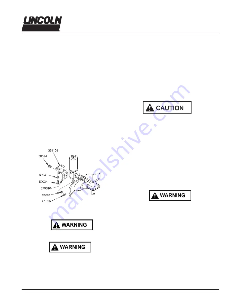
* Included in Spacer Kit 272013
Illustration 4
Do not exceed 450 PSIG (32 bar) working hydraulic
pressure. Use high pressure components to reduce risk of
VHULRXVLQMXU\LQFOXGLQJÀXLGLQMHFWLRQDQGVSODVKLQJLQWKHH\HV
or on the skin. All accessories connected to the pump outlet
must have at least 5,000 PSIG (350 bar) minimum hydraulic
operating pressure. All accessories connected to the pump
inlet must have at least 3,500 PSIG (241 bar) minimum work-
ing pressure.


