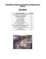


Hints and General Advice to the End-User/Operator
Please be aware that many components and systems in a modern installation are ‘service free’ or
‘lubricated and sealed for life’. This means that although no servicing is required it is still of the
highest importance that these items of equipment are inspected regularly to ensure that they are
sound and still meeting their originally specified performance. Components in a system can become
degraded or damaged by the installation being operated in an inappropriate manner. Regular
inspection by an experienced technician will identify any of these situations before they become
troublesome.
‘The more care taken with the system and component maintenance the greater the reliability and
reduced down-time’
Inspection must be made on a regular basis of the following systems/components:
1. Electrical Control Panels
2. Electronic Control Modules
3. Boiler Flue Side Heat Transfer Surfaces
4. Fuel Pumping and Filtering Systems
5. Flue Dampers and Flue Gas Recirculation (FGR) Systems
6. Air Filters, Fans and Silencers
7. Gas Pressure Control Rigs
8. Flues and Exhaust Ducts
9. Level Controls and Blowdown Systems
10. Refractory Insulation
11. Burner Ignition and Flame Safeguard Systems
Any abnormal occurrence or condition on the system must be investigated by a trained and
technically competent person who has been trained by the manufacturer of the relevant equipment.
A malfunction or abnormal condition would include, Flame Failure, Lockout, High Limit
Temperature/Pressure, Low Gas Pressure, Low Oil Pressure, e.t.c. Any abnormal condition will be
indicated by warning lights or alphanumeric electronics displays, e.t.c. In the interest of safety and
reliability a clear reason must be established for any abnormal condition, system malfunction or
failure before the system can be put back into normal operation. The reason for malfunction and the
recovery procedure must be made and logged by a well trained and technically proficient engineer,
who has received training by the relevant manufacturer.
FAILURE OR IMPROPER SELECTION OR IMPROPER USE OF THE PRODUCTS AND/OR
SYSTEMS DESCRIBED HEREIN OR RELATED ITEMS CAN CAUSE DEATH, PERSONAL
INJURY AND PROPERTY DAMAGE.
Summary of Contents for LC Series
Page 3: ...Section 1 Legal statements and Disclaimers Burner assembly area ...
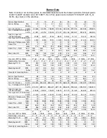
Page 7: ...Section 2 Burner Technical Data Gas flame firing at 12 300 000 btu hr ...
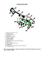
Page 9: ...Section 3 Component Information General assembled burner ...
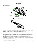
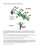
Page 11: ...Section 4 Gas Manifold assembly Split gas head assembly ...
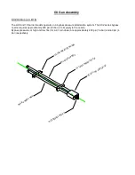
Page 16: ...Section 5 Oil Gun assembly Oil nozzle and lance assembly ...
Page 19: ...Section 6 Electrode settings Pilot injector and ignition setup ...
Page 22: ...Section 7 Burner Installation Limpsfield LC9 dual fuel burners on Hurst boilers ...
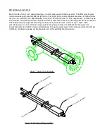
Page 24: ...Sample Typical fire tube installation ...
Page 25: ...Typical water tube installation ...
Page 29: ...Section 8 Typical Gas control Train 2 gas control train assembled ...
Page 32: ...Section 9 Typical Oil Train Assembled oil pump with filter ...
Page 36: ...Section 10 General start up procedure ...
Page 43: ...Section 11 Service Recommendations ...
Page 47: ...Section 12 General Burner Servicing Procedure ...
Page 52: ...Section 13 Fault Finding ...