

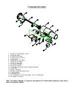


Component Information
8
9
10
5
2
1
4
3
6
7
11
12
13
14
17
16
15
Oi
l R
etu
rn
to
Ta
nk
18
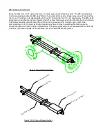
1. Sight Glass Assembly/Access Door
2. Oil Gun Assembly
3. Oil Flow to Lance Hose
4. Oil Return from Lance Hose
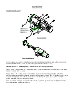
5. Gas Manifold
6. Combustion Air Servo Motor
7. Combustion Air Damper
8. Rear Burner Wind box
9. Front Burner Wind box
10. Blast Tube Assembly
11. Terminal Box Assembly/Transformer Mounting Bracket
12. Terminal Box
13. Ignition Transformer
14. Normally Closed Oil Solenoid Valves
15. Fuel Servo Motor
16. Oil Metering Valve
17. Gas Control valve (Lc9-15 screwed type / Lc21-310 flanged type)
18. Gas Nipple (Lc9-15 only)
Note: The above diagram is a general arrangement for illustrational purposes only. Some
burners may differ slightly.
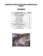
Summary of Contents for LC Series
Page 3: ...Section 1 Legal statements and Disclaimers Burner assembly area ...
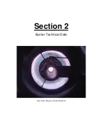
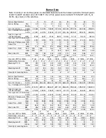
Page 7: ...Section 2 Burner Technical Data Gas flame firing at 12 300 000 btu hr ...
Page 9: ...Section 3 Component Information General assembled burner ...
Page 11: ...Section 4 Gas Manifold assembly Split gas head assembly ...
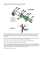
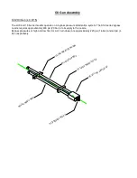
Page 16: ...Section 5 Oil Gun assembly Oil nozzle and lance assembly ...
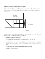
Page 19: ...Section 6 Electrode settings Pilot injector and ignition setup ...
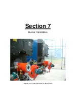
Page 22: ...Section 7 Burner Installation Limpsfield LC9 dual fuel burners on Hurst boilers ...
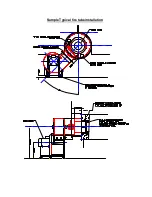
Page 24: ...Sample Typical fire tube installation ...
Page 25: ...Typical water tube installation ...
Page 29: ...Section 8 Typical Gas control Train 2 gas control train assembled ...
Page 32: ...Section 9 Typical Oil Train Assembled oil pump with filter ...
Page 36: ...Section 10 General start up procedure ...
Page 43: ...Section 11 Service Recommendations ...
Page 47: ...Section 12 General Burner Servicing Procedure ...
Page 52: ...Section 13 Fault Finding ...


