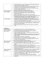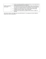
Please follow the instructions below for burner strip down for servicing.
Ensure all Fuel and Electrical supplies to the burner are isolated before commencing with
the procedure listed below. Service work should be carried out by a fully trained service
technician.
1. Remove sight glass assembly/access door by undoing the retaining bolts.
2. Disconnect oil flow to lance connections and remove from the burner (only required on oil)
3. Disconnect oil return to lance connections and remove from the burner (only required on oil)
4. Remove oil lance by loosening the retaining bolts on the rear oil lance support, now the lance can
be removed (only required on oil).
5. Remove oil nozzle and replace o-ring/nozzle as required (only required on oil)
6. Remove Gas manifold by undoing the 4 fixings where the gas manifold meets the burner housing,
remove the manifold ensure care is taken not to damage the ignition lead which has to be
removed as the gas manifold is removed.
7. Check the diffuser plate for any distortion or heat damage and replace as required.
8. Clean any deposits from the diffuser.
9. Clean and check the pilot assembly as required (LC21 and 36 only)
10. Check ignition electrode for cracks or damage.
11. Check the blast tube for heat damage especially the combustion chamber end.
12. Reset ignition and pilot as shown in sections 3 & 5.
13. Check air damper for excessive play on connection to servo motor.
14. Ensure gas manifold o-ring seal is not damaged before re-fitting the gas manifold.
15. Re-assemble burner by reversing steps 6 through to 1
Ensure all fixings and equipment are tight before firing the burner after service work has been carried out.
Once the burner is fired a combustion check must be carried out on both fuels as appropriate.
Oil Pump maintenance
The oil pump is a crucial part of the oil delivery system to enable the burner to operate correctly. The oil to
the pump should be piped from the oil tank to the oil pump via an isolation valve and to a supply oil filter that
is selected to suit the supply pressure and to filter the oil to 40 microns (dependant on site and application).
The oil filter must be well maintained to avoid damage to the pump see section 11 for oil filter maintenance.
Oil supplied should be commercially clean.
Summary of Contents for LC Series
Page 3: ...Section 1 Legal statements and Disclaimers Burner assembly area ...
Page 7: ...Section 2 Burner Technical Data Gas flame firing at 12 300 000 btu hr ...
Page 9: ...Section 3 Component Information General assembled burner ...
Page 11: ...Section 4 Gas Manifold assembly Split gas head assembly ...
Page 16: ...Section 5 Oil Gun assembly Oil nozzle and lance assembly ...
Page 19: ...Section 6 Electrode settings Pilot injector and ignition setup ...
Page 22: ...Section 7 Burner Installation Limpsfield LC9 dual fuel burners on Hurst boilers ...
Page 24: ...Sample Typical fire tube installation ...
Page 25: ...Typical water tube installation ...
Page 29: ...Section 8 Typical Gas control Train 2 gas control train assembled ...
Page 32: ...Section 9 Typical Oil Train Assembled oil pump with filter ...
Page 36: ...Section 10 General start up procedure ...
Page 43: ...Section 11 Service Recommendations ...
Page 47: ...Section 12 General Burner Servicing Procedure ...
Page 52: ...Section 13 Fault Finding ...


