damper is driven to meet the gas input at all times it is advisable to ensure that the combustion O2
levels are in the region of 3 to 4% during this operation. DO NOT open the manual gas cock fully
without checking the combustion throughout this process.
16. Once the manual gas cock is opened the Autoflame flame safeguard controller can be used to drive
open/close the main gas butterfly valve and air damper to ensure safe combustion.
17. The burner gas valve and air damper should be increased to the full input requirement; the air damper
should be adjusted to ensure the combustion sample reads between 2.5 and 3% O2 and must not
exceed the maximum CO concentration by safety standards, which is 400ppm air free. CO
concentration in ppm must not exceed the local permitted levels.
18. The burner “electronic cam” “inter” positions should be commissioned from high fire to low fire in
accordance to the Autoflame technical manual.
19. Start the burner several times to ensure safe and reliable start up, it is also recommended to
modulate the burner from low fire to high fire several times to ensure good flame stability and
combustion throughout the firing range.
20. Once the burner has been commissioned the technician should check and adjust as necessary and
test all gas pressure switches, air pressure switches for correct operation to the manufacturer’s
recommendations. The air pressure switch should be adjusted and set to shut down and cause a
“lockout” to the burner if the air pressure is lower than the commission values.
21. The burner should be re-lit and set to the low fire position, the fuel valves should be turned off, flame
failure should occur resulting in a lockout, all safety shut off fuel valves should be checked to ensure
that they have been de energized and have closed and that the burner package has shut down in a
safe manner.
22. The boiler water levels, high temperature/high pressure limits should be checked to make sure they
turn off the burner as designed and remain in the off condition until the limit or fault has been rectified.
23. If the burner turns off on pressure/temperature due to the Autoflame flame safeguard internal PID, the
burner will turn back on at the pre determined set point (set by the trained technician).
24. If water levels are fitted to the boiler (steam applications) the boiler should be blown down to check
the operation of the water level controls. When the water falls below the set water level the burner
should turn off and restart automatically when the water level is restored to the correct level. With
some applications a low water cut out is employed this will require a manual reset before the burner
turns back on and is not an automatic operation.
Oil start up specifics
Oil Burners
LC9 and 15 burners
The LC9 and LC15 Limpsfield oil burners are designed to have the oil pressurized to 300 psi supplied to the
oil nozzle throughout the firing range including high and low fire. The firing rate is adjusted by a V slot
spillback valve situated in the return oil line after the nozzle. The V slot spillback valve is controlled by a
servo motor which in turn is controlled by an Autoflame Micro Modulation Flame safeguard controller. The
typical spillback pressure at high fire will be in the region of 220 psi. The typical spillback pressure at low fire
will be in the region of 60 to 100 psi.
LC21 and 36 burners
The LC21 and LC36 Limpsfield oil burners are designed to have the oil pressurized to 370 psi supplied to the
oil nozzle throughout the firing range including high and low fire. The firing rate is adjusted by a V slot
spillback valve situated in the return oil line after the nozzle. The V slot spillback valve is controlled by a
servo motor which in turn is controlled by an Autoflame Micro Modulation Flame safeguard controller. The
typical spillback pressure at high fire will be in the region of 310 psi. The typical spillback pressure at low fire
will be in the region of 160psi.
1. Before any start up the technician should check with the local oil supplier for the Btu content of the oil
supplied before calculating the correct oil input. Oil heat content is assumed to be nominally 19,600
Btu/lb. Ultimate CO2 content is assumed to be 15.2%.
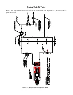
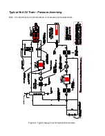
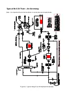
2. Check that oil components and pipe work are connected as per the relevant Oil Train sections in our
O & M manual.
3. Check all equipment supplied meets compliance to relative local or national codes.
Summary of Contents for LC Series
Page 3: ...Section 1 Legal statements and Disclaimers Burner assembly area ...
Page 7: ...Section 2 Burner Technical Data Gas flame firing at 12 300 000 btu hr ...
Page 9: ...Section 3 Component Information General assembled burner ...
Page 11: ...Section 4 Gas Manifold assembly Split gas head assembly ...
Page 16: ...Section 5 Oil Gun assembly Oil nozzle and lance assembly ...
Page 19: ...Section 6 Electrode settings Pilot injector and ignition setup ...
Page 22: ...Section 7 Burner Installation Limpsfield LC9 dual fuel burners on Hurst boilers ...
Page 24: ...Sample Typical fire tube installation ...
Page 25: ...Typical water tube installation ...
Page 29: ...Section 8 Typical Gas control Train 2 gas control train assembled ...
Page 32: ...Section 9 Typical Oil Train Assembled oil pump with filter ...
Page 36: ...Section 10 General start up procedure ...
Page 43: ...Section 11 Service Recommendations ...
Page 47: ...Section 12 General Burner Servicing Procedure ...
Page 52: ...Section 13 Fault Finding ...

