Legal Notice
Operation instruction for Limpsfield Combustion Equipment to guarantee safety, reliability
and efficiency.
The end user should carry out only operational adjustments & routine maintenance. Operational
adjustments would include adjusting temperature or pressure settings on the burner management
system. Maintenance by the end user should be limited to checking peripheral equipment such as
fuel filters, fuel flow meters and fuel supply pressures. Any malfunction of the control system or
burner must be attended to by a qualified technician who has been trained by the manufacturer of
the equipment or his accredited representative. Commissioning, fault finding or any system
equipment modification must absolutely only be implemented by manufacturer trained and approved
technicians/engineers.
Various training schemes can be arranged at or our works or on site with suitably qualified
personnel by prior arrangement with our service support department.
All personnel working on boilers/combustion system should hold suitable qualifications in an
appropriate discipline. All personnel should have received training from the relevant manufacturer.
All personnel should have or be supplied with appropriate clothing i.e. boiler suit, hard hat, safety
glasses and suitably robust foot ware. Any technician/operative must ensure he has access to the
appropriate technical documentation, the correct tools and test equipment to safety and efficiently
deal with the scope of work set out in the job instruction.
If the end user and installer follow the recommendations and instructions set out above the safe,
reliable and efficient operation of the combustion system will be guaranteed and many years of
trouble free operation will be assured.
Summary of Contents for LC Series
Page 3: ...Section 1 Legal statements and Disclaimers Burner assembly area ...
Page 7: ...Section 2 Burner Technical Data Gas flame firing at 12 300 000 btu hr ...
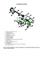
Page 9: ...Section 3 Component Information General assembled burner ...
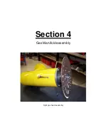
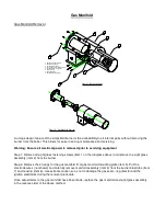
Page 11: ...Section 4 Gas Manifold assembly Split gas head assembly ...
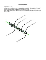
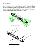
Page 16: ...Section 5 Oil Gun assembly Oil nozzle and lance assembly ...
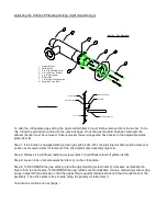
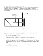
Page 19: ...Section 6 Electrode settings Pilot injector and ignition setup ...
Page 22: ...Section 7 Burner Installation Limpsfield LC9 dual fuel burners on Hurst boilers ...
Page 24: ...Sample Typical fire tube installation ...
Page 25: ...Typical water tube installation ...
Page 29: ...Section 8 Typical Gas control Train 2 gas control train assembled ...
Page 32: ...Section 9 Typical Oil Train Assembled oil pump with filter ...
Page 36: ...Section 10 General start up procedure ...
Page 43: ...Section 11 Service Recommendations ...
Page 47: ...Section 12 General Burner Servicing Procedure ...
Page 52: ...Section 13 Fault Finding ...


