background image


2901544 (16)


Manuel d’entretien

Installation, use and maintenance instructions

Montage und Bedienungs Anleitung


Öl-Gebläsebrenner

Brûleur fioul

Oil burner  


CODE

MODELL - MODELE - MODEL

TYP - TYPE


3743411

G3RK

434T1

D

F

GB

Einstufig
Fonctionnement à 1 allure
One stage operation

Summary of Contents for 3743411

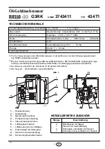
Page 1: ...stallation use and maintenance instructions Montage und Bedienungs Anleitung l Gebl sebrenner Br leur fioul Oil burner CODE MODELL MODELE MODEL TYP TYPE 3743411 G3RK 434T1 D F GB Einstufig Fonctionnem...

Page 2: ......

Page 3: ...h Brennstoff Heiz l EL max Viskosit t bei 20 C 6 mm2 s 1 5 E Stromversorgung Einphase 230V 10 50Hz Motor Stromaufnahme 0 70A 2850 U min 298 rad s Kondensator 4 mF Z ndtransformator Sekund rspannung 8...

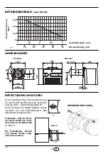
Page 4: ...150 4 5 Flansch Brenner Es ist unbedingt n tig da zwischen Kessel t r und Flansch des Brenners die Isolierdich tung 9 Abb 1 dazwischengef gt wird Diese Dichtung hat sechs L cher welche eventuell wie a...

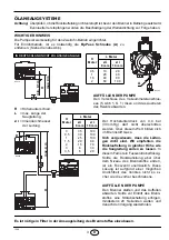
Page 5: ...r beschriebene AUFF LLEN DER PUMPE Den Brenner starten und das Auff llen abwarten Sollte vor Eintritt des Brenn stoffes eine St rabschaltung erfolgen mindestens 20 Sekunden warten und danach den Vorga...

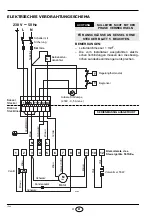
Page 6: ...ste des Steuerger ts 531SE SERIENM SSIG AUSGEF HRT Kessel Stecker Brenner Steckdose 3 4 5 6 7 8 9 N L Gelb Gr n Blau Blau Braun Schwarz h Schwarz ACHTUNG NULLEITER NICHT MIT DER BEMERKUNGEN Leiterdurc...

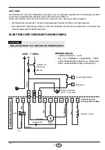
Page 7: ...n und dabei das unten aufgezeigte Schema beachten ELEKTRISCHES VERDRAHTUNGSSCHEMA ACHTUNG NULLEITER NICHT MIT DER PHASE VERWECHSELN Braun Weiss 50V Blau Motor Kondensator Regelungthermostat Nulleiter...

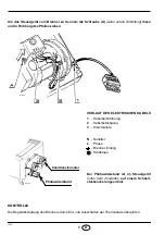
Page 8: ...schaltung des Brenners durch Ein und Ausschalten der Thermostate berpr fen VERLAUF DES ELEKTRISCHEN KABELS 1 Kabeldurchf hrung 2 Kabelbefestigung 3 Klemmleiste N Nulleiter L Phase Brenner Erdung St rl...

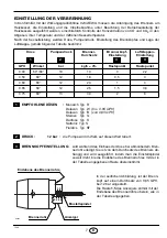
Page 9: ...mpe wird im Werk auf diesen Wert tariert BRENNKOPFEINSTELLUNG wird w hrend des Einbaus der D se bei abmontiertem Bren nerrohr erledigt Sie ist von dem Durchsatz des Brenners ab h ngig und wird ausgef...

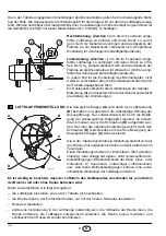
Page 10: ...durch den Luftsteuerung B betrieben und garantiert die vollst ndige ffnung der Ansaug ffnung Der Luftdurchsatz wird durch die Bet ti gung der unbeweglichen Klappe C reguliert Zu diesem Zweck m ssen z...

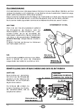
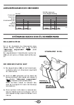
Page 11: ...an der Grundplatte des Steuerger ts angebrachten Stecker wegnehmen und diesen in die ausgeschaltete Vorw rmewi derstand Stellung waagrechtweise wiederein stecken In diesem Fall f hrt der Brenner bei S...

Page 12: ...rochen 2 Wenn die LED aufleuchtet und der Motor des Brenners dennoch nicht anl uft den Stecker in die Position Widerstand ausgeschaltet umstecken siehe seitliche Abb Wenn der Motor anl uft so bedeutet...

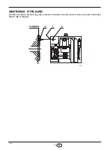
Page 13: ...1544 11 D WARTUNGS STELLUNG Den Bolzen 2 in die Bohrung 1 einsetzt und danach den Brenner mit der verkehrt montierten Mutter 3 verriegeln 3 1 2 FLANSCH D5325...

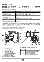
Page 14: ...1 5 E Alimentation lectrique Monophas e 230V 10 50Hz Moteur Courant absorb 0 70A 2850 t min 298 rad s Condensateur 4 mF Transformateur d allumage Enroulement secondaire 8 kV 16 mA Pompe Pression 7 15...

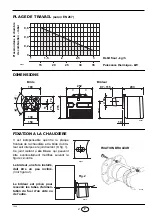
Page 15: ...180 75 72 150 4 5 Bride Br leur Il est indispensable qu entre la plaque frontale de la chaudi re et la bride du br leur soit interpos le joint isolant 9 fig 1 Ce joint isolant a six trous qui peuvent...

Page 16: ...l d faut d tanch it de la vanne AMOR AGE POMPE Faire d marrer le br leur et attendre l amor age En cas de mise en s curit avant l arriv e du combustible attendre au moins 20 secondes apr s quoi r p te...

Page 17: ...T T D5330 Noir avec fusible R sistance 55W Bornier de la bo te de contr le 531SE EXECUTEE EN USINE Fiche chaudi re Prise br leur 3 4 5 6 7 8 9 11 10 12 N L Jaune vert Rouge Rouge Bleu Bleu Marron Noir...

Page 18: ...ENT ELECTRIQUE ATTENTION NE PAS INVERSER LE NEUTRE AVEC LA PHASE Marron Blanc 50V Bleu Moteur Condensateur Thermostat de r glage Neutre 6A max N L M Noir N L 1 2 3 4 5 6 7 8 9 Bleu Marron Vanne T T D5...

Page 19: ...en ouvrant les circuits des thermostats TRAJET DU CABLE ELECTRIQUE 1 Presse toupe 2 Blocage c bles 3 Bornier N Neutre L Phase Terre br leur Lampe s curit La cellule photor sistance est mon t e direct...

Page 20: ...ic type S Fluidics type SF PRESSION 12 bar la pompe sort de l usine calibr e cette valeur REGLAGE TETE DE COMBUSTION Il est fait au moment du montage du gicleur avec gueulard d mont Il d pend du d bit...

Page 21: ...ompter les tours REGLAGE VOLET D AIR Le volet d air mobile A command par le v rin B don ne l ouverture compl te de la bo te d aspiration de l air La r gulation du d bit se fait par le volet fixe C apr...

Page 22: ...leur ou si la temp rature ambiance ne l exige pas etc enlever la fiche plac e sur le panneau de la bo te et la r ins rer sur R sistance OFF Dans ce cas le d marrage du br leur a lieu la fermeture des...

Page 23: ...nte plac e sur le porte gicleur est coup e 2 Si le LED est illumin mais le moteur ne d mar re pas il faut commuter la fiche dans la position R sistance OFF voir figure Si le moteur d marre a signifie...

Page 24: ...1544 11 F POSITION D ENTRETIEN Introduire le boulon 2 dans le trou 1 et bloquer le br leur au moyen de l crou 3 mont l arri re 3 1 2 BRIDE D5325...

Page 25: ...mm2 s 1 5 E Electrical supply Single phase 230V 10 50Hz Motor Run current 0 70A 2850 rpm 298 rad s Capacitor 4 mF Ignition transformer Secondary 8 kV 16 mA Pump Pressure 7 15 bar Absorbed electrical p...

Page 26: ...0 4 5 Flange Burner It is necessary that the insulating gasket 9 fig 1 is placed between the boiler door and the burner flange This insulating gasket has six holes which if necessary can be modified a...

Page 27: ...PRIMING THE PUMP Start the burner and wait for the priming Should lock out occur prior to the arrival of the fuel await at least 20 seconds before repeating the operation A filter must be installed o...

Page 28: ...resetting Remote lock out lamp 230V 0 5A max if required 1 N T1 T2 S3 B4 Brown Valve T T D5330 Black CARRIED OUT IN THE FACTORY Boiler plug Burner socket N L Yellow Green Blue Blue Brown Black Hour c...

Page 29: ...BURNER ELECTRICAL WIRING Brown 1 2 3 4 5 6 7 8 9 Terminal block of control box 531SE Red Red 11 10 12 Heater 55W WARNING DO NOT EXCHANGE THE NEUTRAL WITH THE PHASE White 50V Blue Motor Capacitor Regu...

Page 30: ...t down of the burner by opening the thermostats RUN OF THE ELECTRICAL CABLE 1 Cable gland 2 Cable clamp 3 Terminal block N Neutral L Phase Burner earth Lock out lamp The photoresistance is fitted dire...

Page 31: ...pe S Satronic type S Fluidics type SF PRESSURE 12 bar The pump leaves the factory set at this value COMBUSTION HEAD SETTING This is done when fitting the nozzle with the blast tube removed It depends...

Page 32: ...ing the number of turns AIR DAMPER ADJUSTMENT The mobile air damper A operated by the jack B as sures the complete opening of the air intake The regulation of the air rate is made by adjusting the fix...

Page 33: ...t require it etc take the plug off the panel of the control box and plug it in to the Resistance OFF In this case the burner starts up when the ther mostats close NOTE The warning light LED is ON but...

Page 34: ...in the nozzle holder is off 2 If the LED is ON and nevertheless the burner does not run place the plug in the position cor responding to Resistance OFF see drawing on the right If the motor runs the d...

Page 35: ...1544 11 GB MAINTENANCE POSITION Insert in the hole 1 the pin 2 and fix the burner with the nut 3 fitted wrong side up 3 1 2 FLANGE D5325...

Page 36: ......

Reviews: