Lightware UMX4x4-Pro User Manual Download Page 38


Page 38 / 129 

Section 

4

Operation


Navigate to the ‘Input 1 Return’ item then press the ENTER 

 button to step back to 

the input port settings. 

6) 

Navigate  to  the  ‘Return’  item  then  press  the  ENTER 


button to step back to the main menu. 

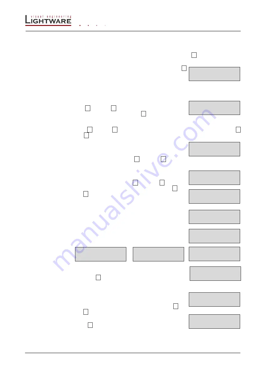
Output settings 

Navigate to this menu in the main menu list. 

Select the output port 

Use the up 

▲ and down ▼ buttons to select the port that needs 

adjustment and then press the ENTER 

 button. 

Output port settings submenu 

Use the left 

◄ and right ► buttons to select the parameter to be changed. Use the up ▲ 

and down 

▼ buttons to change the value.  

1)  Mode: 

The  ‘Mode’  can  be  set  to  Auto,  DVI,  HDMI  24bit, 

HDMI 30bit or 

HDMI 36bit. The ‘Auto’ option sets the signal 

mode regarding to the attached display device’s EDID and 
the incoming signal. Use the up 

▲ and down ▼ buttons to 

change the value. 

2) 

Analog audio….: The ‘Analog audio….’ Submenu contains 
the attributes of the analog audio signal which is connected 
to  the  input  port.  Use  the  left 

◄  and  right  ►  buttons  to 

select  the  parameter  to  be  changed.  Use  the  up 

▲  and 

down 

▼ buttons to change the value. 

a.  Volume: from 0 dB to -78 dB 

b.  Balance: from 0% to 100% 

c.  Bass: from 0 dB to 24 dB with 2dB steps 

d.  Treble: from 0 dB to 6 dB with 2 dB steps 

e.  Deemphasis: Enabled or disabled 

f. 

Output phase: 0 or 180 degree 


g.  Return 

Navigate to the ‘Output 1 Return’ item then press the 
ENTER 

  button  to  step  back  to  the  output  port 

settings 

3) 

The  ‘HDCP’  option  sets  the  HDCP  encryption  on  the 
output.  The  Auto  setting  applies  encryption  when  the 
incoming  signal  is  encrypted.  The  Always  setting  forces 
encryption on any incoming video signal. Use the up 

▲ and 

down 

▼ buttons to change the value. 

4)  Return:  Navi

gate  to  the  ‘Return’  item  then  press  the 

ENTER 

 button to step back to the out port settings. 


Output settings 
Output  # 

Output # 
Mode: Auto 

Output # 
Analog audio.... 

Output # 
Volume:-0dB 

Output # 

Balanve:50% 

Output # 

Bass:0 dB 

Output # 
Treble:0 dB 

Output # 
Deemphasis:Disab 

Output # 
Output phase:0 

Output # 
Return 

Output # 
HDCP:Auto 

Return 


Output # 

Return 

Summary of Contents for UMX4x4-Pro

Page 1: ...UMX4x4 Pro User s Manual...

Page 2: ......

Page 3: ...ns described in this manual Ventilation For the correct ventilation and avoid overheating ensure enough free space around the appliance Do not cover the appliance let the ventilation holes free and ne...

Page 4: ......

Page 5: ...tors 22 3 3 6 Analog stereo audio input and output connectors 22 4 OPERATION 23 4 1 POWER 23 4 2 FRONT PANEL OPERATIONS 23 4 2 1 Signal layers 23 4 2 2 TAKE AUTOTAKE modes 23 4 2 3 CONTROL LOCK 23 4 2...

Page 6: ...s 66 6 3 6 Quick I O port information 67 6 3 7 Switch mute and lock 68 6 3 8 Preset operations 68 6 3 9 Input parameter settings 69 6 3 10 Output parameter settings 72 6 4 EDID MENU 73 6 4 1 Change em...

Page 7: ...ion on all outputs 93 7 8 6 Mute specified output 94 7 8 7 Unmute specified output 94 7 8 8 View mutes on all outputs 94 7 8 9 Lock specified output 94 7 8 10 Unlock specified output 94 7 8 11 Save pr...

Page 8: ...ut audio properties 109 7 12 ERROR RESPONSES 109 8 FIRMWARE UPGRADE 110 8 1 INSTALLING THE BOOTLOADER 110 8 1 1 Installing and launching the Bootloader software 110 8 2 UPGRADE PROCESS 112 8 2 1 Tips...

Page 9: ...e switcher s inputs independently read out and store any attached monitor s EDID in 100 internal memory locations upload and download EDID files using Matrix Control Software Non blocking cross point...

Page 10: ...monitor incoming signal parameters such as resolution signal timing parameters color space audio type scan rate HDCP encryption and so on Deep Color support and conversion It is possible to transmit t...

Page 11: ...Typical applications Some typical connection variations with the matrix router are shown on Figure 2 1 Figure 2 1 Typical application for UMX4x4 Pro Application examples Small classrooms Conference ro...

Page 12: ...ed Timings audio capabilities speaker allocation and HDMI capabilities It is important to know that all HDMI capable devices must have CEA extension but not all devices are HDMI capable which have the...

Page 13: ...emulates 150 EDID data plus all monitor s EDID that are connected to the output connectors First 100 EDID are factory presets while memories 100 to 150 are user programmable The router stores the EDI...

Page 14: ...r 5 8 seconds The HDCP key cashing technique avoids this and allows instantaneous switching between two encrypted signals 2 6 3 Avoiding unnecessary HDCP encryption Many video sources send HDCP protec...

Page 15: ...xel Accurate Reclocking Signal reclocking is an essential important procedure in digital signal transmission After passing the reclocking circuit the signal becomes stable and jitter free and can be t...

Page 16: ...in the time domain The time difference between two signal transitions should be a fix value but noise and other effects cause variations Noise electromagnetic interference between other electronic dev...

Page 17: ...gnals are on different layer so they can be switched at the same time or separately Layer select buttons chose the desired signal s what will be switched Source buttons Source buttons have three funct...

Page 18: ...digital pins are connected Analog audio out Double RCA jack connector for analog stereo audio output signal with right and left channel S PDIF out RCA jack connector with S PDIF digital audio signal...

Page 19: ...C3 Analog Blue 1 C4 Analog Horizontal Sync 1 C5 GND Table 3 1 DVI I connector pin assignments Figure 3 3 DVI connector 1 These pins are connected only on the DVI inputs 3 3 2 DVI outputs 29 pole DVI...

Page 20: ...control port Figure 3 4 D SUB 9 pole female connector DE9F Pin nr RS 232 1 NC non connected 2 TX data transmit output 3 RX data receive input 4 DTR Internally connected to Pin 6 5 GND signal ground s...

Page 21: ...reen full duplex 100 Mbps Blink activity N A Figure 3 5 RJ45 receptacle connector Figure 3 6 RJ45 plug Lightware recommends the termination of TP cables on the basis of TIA EIA T 568 A or TIA EIA T 56...

Page 22: ...utput connectors UMX4x4 Pro has standard RCA receptacle for analog stereo audio inputs and outputs Inputs and outputs work with standard line in and line out voltage levels RCA plug left channel RCA r...

Page 23: ...inuously If only one layer was selected and the associated button is pressed the layer will be deselected and the other layer will be selected Before every operation which effects input and output sig...

Page 24: ...was selected in last 3 seconds user can verify both input and output connections for any layer This informative display will remain for 3 seconds and then all button lamps go out In TAKE mode no accid...

Page 25: ...nd all destination buttons which are currently connected to this source will light up The dark remaining destination buttons are not connected to this source This is an informative display about curre...

Page 26: ...witching flowchart in TAKE mode AUTOTAKE mode Figure 4 2 Switching flowchart in AUTOTAKE mode idle TAKE mode TAKE button pressed connections realized previewing connections source button pressed viewi...

Page 27: ...r all outputs including mute state but ignoring lock state Loading a Preset in TAKE mode Step 1 Press and release LOAD PRESET button Step 2 Press and release a source button according to the desired m...

Page 28: ...KE mode Step 1 Select the desired layer Video or audio or both of them Step 2 Press and release the Output Lock button Step 3 Now the Output Lock button starts to blink and all the locked output s but...

Page 29: ...o or both of them Step 2 Press and release the required destination button Now the selected destination button and the currently configured source button light up view mode Step 3 Press and release th...

Page 30: ...nfo UMX4x4 Pro can handle both 128 Byte EDID and 256 Byte extended EDID structures Info The attached monitor s EDID is stored automatically until a new monitor is attached to that particular output In...

Page 31: ...9 Hz Analog F21 1600 x1200 60 0 Hz DVI F70 1400 x1050 49 99 Hz Analog F22 1920 x1200 50 0 Hz DVI F71 1400 x1050 59 99 Hz Analog F23 1920 x1200 59 55 Hz DVI F72 1400 x1050 75 0 Hz Analog F24 2048 x1200...

Page 32: ...ode is for checking the presence of the display devices and incoming signals Enter or exit this mode by pressing the SIGNAL PRESENT button The illuminated button shows that this mode is active 4 4 2 M...

Page 33: ...CP and fix IP address If the DHCP is switched off then the IP address can be set by the user The four part of the fix IP address can be set separately Use the left and right buttons to select the part...

Page 34: ...n number Press left and right buttons to select another menu item RS 232 settings menu The serial port baud rate value can be set here Press the ENTER and use the up and down buttons to change the bau...

Page 35: ...u IP reset submenu This operation reloads the factory default IP settings Parameter Default value IP address fix 192 168 254 254 port number 10001 Subnet mask 255 255 0 0 Gateway 0 0 0 0 Press the ENT...

Page 36: ...ideo signal type which is connected to the input port It can be set to Auto Digital Analog YUV Analog RGB or Analog auto Use the up and down buttons to change the value The Auto source setting accepts...

Page 37: ...log video menu Info The Analog video submenu available only if there is a valid analog audio signal on the current input port Info UMX4x4 Pro examines the analog video signal on the input port and adj...

Page 38: ...g audio signal which is connected to the input port Use the left and right buttons to select the parameter to be changed Use the up and down buttons to change the value a Volume from 0 dB to 78 dB b B...

Page 39: ...step in submenus Info You can cancel any not yet executed operation by exiting the EDID menu with pressing the EDID button Info Source and destination buttons are disabled while EDID mode is active V...

Page 40: ...on done message is shown for 2 seconds 4 4 6 Signal Present mode To enter or exit this mode you have to press the SIGNAL PRESENT button Signal present mode is active when Signal present button is illu...

Page 41: ...er information Ethernet port RS 232 serial port Lightware matrix controller software chapter 0 on page 44 Built in website no chapter 6 on page 64 third party control system chapter 7 on page 80 Table...

Page 42: ...UTOTAKE mode by pressing TAKE button for 3 seconds light will go off Step 2 Press and hold down the Control Lock button for 3 seconds Control Lock button lights in up red continuously Step 3 Press and...

Page 43: ...e Output Lock button Now the active protocol is displayed view protocol One source button lights up according to the current protocol Source 1 lights Lightware protocol active on Serial Source 2 light...

Page 44: ...rom a Windows PC or Laptop through RS 232 or Ethernet port 5 1 Installing the Matrix Controller software Step 1 Run Installer_LW_matrix_controller_v3_3_9 exe Step 2 Select destination folder and click...

Page 45: ...net port Step 1 Connect the matrix switcher and the computer either via Serial port with RS 232 Male to Female cable straight through Ethernet with LAN patch cable to a Hub Switch or Router Ethernet w...

Page 46: ...d the serial number are displayed automatically Click the desired device to highlight it If the computer has more Ethernet ports for example WiFi and LAN connections are used simultaneously you must s...

Page 47: ...thernet box try searching again or see the trouble shooting guide in section 9 3 about TCP IP connection problems on page 123 Info Be sure that the firewall is not blocking the application When the Li...

Page 48: ...more outputs simultaneously there can be one or more green squares in one column However an output can be switched to only one input so there can be only one green square in any row 5 3 1 Port status...

Page 49: ...about the port status The port name the incoming signal and connection status can be checked Output status shows only port name and connections 5 3 4 Switch mute and lock For making a connection clic...

Page 50: ...1 Make the desired crosspoint connections on the matrix switching area Step 2 Select the preset memory Preset1 Preset32 where you want to save your current crosspoint connections Step 3 Press SAVE PRE...

Page 51: ...rresponding input Figure 5 5 Input parameters for digital signal Scope of changes There are two options to apply changes To set the scope of the changed settings select the desired option in the top l...

Page 52: ...ly unprotected content can be played on the source if this setting is disabled For more information about HDCP handling see section 2 6 on page 14 No sync color The port generates a solid 640x480 reso...

Page 53: ...o signal HDCP encryption the source 5V sync type Video Resolution color depth and color space of the incoming signal are shown here The Timing type and Timing ID fields show which parameters are used...

Page 54: ...Page 54 129 Section 5 Software control Using Lightware Matrix Controller Frame detector Click the frame detector button to view the measured detailed timings on the incoming signal...

Page 55: ...plied to all output ports Info When opening this window again the scope selection will be set to Current Output regardless of the active selection at the time of closing It is to avoid making changes...

Page 56: ...splayed on either side by using the drop down lists The Emulated EDID List shows the currently emulated EDIDs for each input It contains the resolution manufacturer and vendor name of the EDID reporte...

Page 57: ...is feature helps especially rental technicians or system integrators to keep the source continuously transmitting the signal and adopt the system for new incoming display devices Info Power ON OFF cyc...

Page 58: ...tool is essential for AV professionals The Lightware Advanced EDID Editor is integrated into the Lightware Matrix Controller software and it makes possible to manage every setting in the EDID on an i...

Page 59: ...stablished with a router this terminal can be used either via serial or TCP IP connection All commands can be used here that are discussed in the Programmers reference chapter 7 on page 80 The text ca...

Page 60: ...ards firmware and hardware revisions are displayed in this window Figure 5 9 Status menu Info If the device is connected via RS 232 the IP address field shows serial connection instead of the IP addre...

Page 61: ...e router and the Matrix Controller Software Step 4 Click to the Close button to close this window and step back to the Status menu Info The Load Default button loads the factory default IP settings to...

Page 62: ...default file name is Lightware_matrix_standard_report_dd_mm_yyyy hh_mm lwr User s issues can be solved easier by Lightware technical support if the generated report file was sent During the process a...

Page 63: ...will be saved Important Let the Lightware Matrix Controller software to finish the process Do not exit or select another menu item During the process a big red message will be appeared 5 7 Find menu B...

Page 64: ...simultaneously Other TCP IP connections are prohibited while the web page is opened Using more instances of the web page simultaneously will result in inadequate operations Info Some of the Lightware...

Page 65: ...le rows are the outputs The green squares represent the state of the matrix switcher The Preset selection box is on the right side of this page Input or output parameter windows can be reached by clic...

Page 66: ...udio Output 1 Audio Output 4 rows represent the audio outputs Each green square represents an active connection Since an input can be routed to more outputs simultaneously there can be one or more gre...

Page 67: ...ER to apply changes Read I O names I O names are loaded automatically when connection to the router is established and shown in the control menu window To reload the port names refresh the webpage wit...

Page 68: ...s it is unlocked again If output lock is active the color of the button s background changes to red Info Loading a preset doesn t alter either the lock state or the switch state of a locked output If...

Page 69: ...set is stored 6 3 9 Input parameter settings By clicking on an input label a dialog window appears showing the parameters for the corresponding input Figure 6 2 Input settings for digital signal Scope...

Page 70: ...lick to OK button to apply changes Click to Cancel button to discard changes and close the window Audio source The audio signal type of the connected source can be selected in this drop down list Mute...

Page 71: ...default values to the currently selected input All inputs Loads the factory default values to all inputs Analog video options Analog video signals are digitized on the input The timing parameters can...

Page 72: ...gain the scope selection will be set to Current Output regardless of the active selection at the time of closing It is to avoid making changes to all outputs by mistake Reload factory defaults Current...

Page 73: ...time After the list is downloaded the current status of the router s EDID is shown in the three boxes The Emulated EDIDs box contains the resolutions and the vendor names of the EDID reported to the s...

Page 74: ...box shows on the left corner Figure 6 5 Static EDID routing Info Switching an EDID to ALL inputs may take several seconds Switching an EDID from Monitor 1 Monitor 4 called as Last Attached Monitors E...

Page 75: ...DID from the list Step 2 Click the Learn this EDID to submenu item A popup window will show the memory locations from 90 to 139 which are available for the user Step 3 Click on the desired memory loca...

Page 76: ...alled cards firmware and hardware revisions are displayed in this window Figure 6 8 Status menu 6 6 Configuration The unit s network values are displayed when you select Configuration menu Info It is...

Page 77: ...ort Step 4 When you are finished click Apply Settings button Info To continue using the built in website you must type in the IP address in your browser 6 6 2 Static IP address configuration The user...

Page 78: ...can configure the TCP port number which is used to communicate with the matrix router through LAN The input box initially contains the current setting Step 1 Type the desired TCP port number into the...

Page 79: ...programmers reference chapter 7 on page 80 The text can be typed directly into the textbox By default commands are automatically surrounded by framing brackets Every sent command and every received re...

Page 80: ...4 5 5 or with protocol commands 7 2 Protocol description The protocol description hereinafter stands for Lightware protocol The matrices accept commands surrounded by curly brackets and responds with...

Page 81: ...k 12 0C FF 44 2C 76 4C L 108 6C l 13 0D CR 45 2D 77 4D M 109 6D m 14 0E SOH 46 2E 78 4E N 110 6E n 15 0F SI 47 2F 79 4F O 111 6F o 16 10 DLE 48 30 0 80 50 P 112 70 p 17 11 DC1 49 31 1 81 51 Q 113 71 q...

Page 82: ...sic error list cleared on reboot 7 4 Status and identification commands 7 4 1 View product type Description Identification of the device Type i or I then the router responds its name Format Example Co...

Page 83: ...esponse CF TYPE VER INFO CrLf CF END CrLf CF MX CP FW 2 0 6 0X10 CrLf CF END CrLf Legend TYPE Installed controller s type VER The controller s firmware version INFO Optional information about controll...

Page 84: ...inal 5V INNER TEMPERATURE Explanation Internal voltages and temperature shown 7 4 10 View installed I O boards Description Shows the hardware name and revision of the installed cards The number of res...

Page 85: ...l operation These entries do not mean that there is any problem with the matrix 7 5 System commands 7 5 1 Reload factory defaults Description Factory default settings can be reloaded for different fun...

Page 86: ...d num the number of the HDCP keys Explanation The source on the 2nd input can handle 8 HDCP sink devices 7 5 3 Clear HDCP key cache Description The matrix stores the HDCP keys from the connected devic...

Page 87: ...Description This command sets the router to the factory default IP setup Format Example Command IP_CONFIG ip_config Response Changing IP configuration CrLf Changing IP configuration CrLf DONE CrLf or...

Page 88: ...Example Command loc1 loc2 e4 f10 Response E_SW_OK CrLf delay E_S_C CrLf E_SW_OK CrLf delay E_S_C CrLf Legend loc1 has to be Exx loc2 can be Fxx or Uxx or Dxx Explanation Factory EDID F10 is copied to...

Page 89: ...nput 2 F029 Factory preset EDID F29 is emulated on the input 3 U007 User saved EDID U7 is emulated on input 4 7 7 5 Watch EDID validity table Description Shows EDID validity table which contains infor...

Page 90: ...input 1 7 7 7 Download EDID content from the router Description EDID hex bytes can be read directly The router will issue the whole content of the EDID present on memory location loc 256 bytes Format...

Page 91: ...EDID uploaded to memory location U3 7 7 9 Delete EDID from memory Description Clear EDID from memory location loc Format Example Command DE loc deu Response DE_OK CrLf E_S_C CrLf DE_OK CrLf E_S_C CrL...

Page 92: ...ow example shows a batch command that resulted group switching One by one commands Batch commands UMX4x4 02 01 CrLf 02 01 04 03 CrLf O01 I02 CrLf O01 I02 CrLf O03 I04 CrLf 04 03 CrLf O03 I04 CrLf 7 8...

Page 93: ...ltilayer command 7 8 5 View connection on all outputs Info The response shows connections only for the video layer 7 8 5 View connection on all outputs Description This command displays all connection...

Page 94: ...8 8 View mutes on all outputs Description Viewing all outputs mute state Format Example Command VM vm Response ALL M1 M2 M3 M4 CrLf ALL 1 0 0 0 CrLf Legend All Mx indexes are one digit numbers showing...

Page 95: ...ng to preset 4 including the mute state of the outputs It is possible to load only one layer in that case other layer crosspoint will be not affected 7 8 13 View preset Description View the id numbere...

Page 96: ...is FIRST PRESET 7 8 18 Read an input s name Format Example Command INAME in iname 3 Response INAME in input_name CrLf INAME 3 MEDIA PLAYER CrLf Explanation Name for input 3 is MEDIA PLAYER 7 8 19 Read...

Page 97: ...number represents the state for the corresponding input port The binary representation of the responded decimal numbers is shown below 3 bit MSB 2 bit 1 bit 0 bit LSB UMX4x4 Pro Analog signal HDCP act...

Page 98: ...can stay untouched To mask a parameter use x or X as its value Example DVII 1 SI D x x x Set input port no 1 to digital ADC 1 SI x 1 x Turn on polarity inversion on input port 1 7 10 1 Set input port...

Page 99: ...are two characters The second one is the active audio source 0 No audio H Audio from HDMI source A Analog audio from analog input S Digital audio from SPDIF input Source dependent parameters Analog s...

Page 100: ...M PCM signal present 0x00 FR FL 0x01 LFE FR FL 0x02 FC FR FL 0x03 FC LFE FR FL 0x04 RC FR FL 0x05 RC LFE FR FL 0x06 RC FC FR FL 0x07 RC FC LFE FR FL 0x08 RR RL FR FL 0x09 RR RL LFE FR FL 0x0A RR RL FC...

Page 101: ...esponse DVII in S A I VIDEO X AUDIO HDCP STATUS SOURCE ATIM1 DCS ATIM2 DRES ARES HAUDIO HASAMP HCH CrLf DVII 1 SI S A H 0 1 HH 20 1920x1080p24 M 48 0B CrLf Legend Please read section 7 10 1 Set input...

Page 102: ...tal Size HS Horizontal Size VS Vertical Size HP Horizontal Position VP Vertical Position Info The following parameters cannot be set they only appear in response LCF Full Vertical Size Line Count per...

Page 103: ...CONT SAT BRIGHT HUE picture 3 si 1023 1023 1023 1023 1023 1023 1023 1023 1023 128 128 0 0 CrLf Response PICTURE in S A I DF_CHA DF_CHB DF_CHC G_CHA G_CHB G_CHC O_CHA O_CHB O_CHC CONT SAT BRIGHT HUE Cr...

Page 104: ...023 1023 1023 128 128 0 0 CrLf Legend Please read section 7 10 1 Set input port properties 7 10 10 Reset analog color properties Description Reset analog color properties of the input ports Format Exa...

Page 105: ...s S single selected input A all outputs RED Red component of RGB value GREEN Green component of RGB value BLUE Blue component of RGB value Explanation The example shows how to set yellow colored monoc...

Page 106: ...24 bit AUDIO 1 SO x x 20 x x x Turn on bass enhancement 20dB 7 11 1 Set output video properties Description This command is for configuring output port settings Format Example Command HDMI out S A O M...

Page 107: ...ul REP 0 Attached device is not an HDCP repeater 1 Attached device is an HDCP repeater YUV4 0 Attached device does not support YUV 4 4 4 1 Attached device supports YUV 4 4 4 YUV2 0 Attached device doe...

Page 108: ...22 500 20 4 1 0 Response AUDIO out S A O RVOL LVOL BASS TREBLE PREEMP INVERT CrLf AUDIO 1 SO 422 500 20 4 1 0 CrLf Legend S A S single selected output A all outputs RVOL reduce right volume in dB 100...

Page 109: ...ad section 7 11 3 Set output audio properties 7 12 Error responses Invalid input number Description Given input number exceeds the maximum number of inputs or equals zero Invalid output number Descrip...

Page 110: ...the Bootloader UMX4x4 Pro can be upgraded using Lightware Bootloader from a Windows based PC or Laptop via Ethernet 8 1 1 Installing and launching the Bootloader software Step 1 Run Installer_LW_bootl...

Page 111: ...the files have been copied the following message appears Step 5 To finish the installation process click on the Close button Step 6 To run Lightware Bootloader find the shortcut icon in Start menu Pro...

Page 112: ...r send noise through the cable which may interfere with the upgrade process Latest Bootloader Always perform the firmware upgrade with the latest Bootloader software To get the latest Bootloader softw...

Page 113: ...Lightware folder Figure 8 1 Bootloader software startup Step 3 Find devices Make sure that no active connection is made to the device Lightware Matrix Controller software or web browser connected to t...

Page 114: ...vice will become the primary adapter and the Bootloader can query it for Lightware devices If you disable an Ethernet adapter while the Bootloader is running you need to restart the Bootloader to be a...

Page 115: ...ou really want to connect to the device Select YES to establish the connection It will take 10 15 seconds to get all the information from the Lightware device After establishing the connection the dev...

Page 116: ...ntroller types are described in the table below Now you can browse for the new firmware file to upload After opening the new file the new firmware field will contain the name of the firmware file Cont...

Page 117: ...e the upgrade by clicking the checkbox left to the controller type marked with a red circle in the picture below You may enable Quick Bootload mode by clicking the checkbox next to it marked with a re...

Page 118: ...Enabling the upgrade and Quick Bootload mode Step 8 Starting the upgrade process After selecting all the firmwares that need to be upgraded click on the UPGRADE SELECTED FIRMWARES button Then click o...

Page 119: ...rting the upgrade process Step 9 Upgrading The Bootloader will first erase the content of the controllers and then write the new firmware data This process can be monitored in the communication window...

Page 120: ...trollers are upgraded the Bootloader will close the connection with the Lightware device which will reboot itself and return to its normal operating mode Warning Bootloader versions that are older tha...

Page 121: ...e 8 10 Closing connections Step 11 Upgrade successful If the connections are closed and no errors occurred the firmware upgrade is SUCCESSFUL Click on the OK button and then you may exit the Bootloade...

Page 122: ...mware upgrade Figure 8 11 Upgrade successful Step 12 Restart the device The Lightware device will restart itself automatically but it is recommended to completely power down and power up the device af...

Page 123: ...ype If you connect the router directly to your computer you must use a cross link cable If the matrix is connected to an Ethernet hub switch or router you have to use a straight patch LAN cable Check...

Page 124: ...ou have to review the driver settings 9 5 Bootload The Bootloader cannot find the matrix The Bootloader software always queries the PC s primary Ethernet adapter which is usually the adapter that is c...

Page 125: ...grade on the different controller types An invalid file has been selected The Bootloader checks if valid firmware files have been selected for the controllers If an invalid file not firmware file has...

Page 126: ...t type NLP70 Power consumption max 40 W 137 BTU hour AC power connector IEC C14 receptacle Enclosure Rack mountable Yes 1U high Material 1 mm steel Dimensions in mm 446 482 W x 302D x 44H Dimensions i...

Page 127: ...orts Number 4 Connector type RCA Digital video signal Signal standard DVI or HDMI standard which supports Deep color Embedded audio Color depth maximum 36 bits 12 bit color Color format RGB YCbCr 4 4...

Page 128: ...Page 128 129 Section 10 Specifications 10 1 Mechanical Drawings Front View Rear View Top View Right View 482 00 mm 43 90 mm 482 00 mm 43 90 mm 482 00 mm 302 00 mm 446 00 mm 302 00 mm 43 90 mm...

Page 129: ...arranty Lightware Visual Engineering warrants this product against defects in materials and workmanship for a period of three years from the date of purchase The customer shall pay shipping charges wh...

Reviews: