background image

Client program


53

Mail Settings

Set the mail options.

Notification: When you mark up the notification option, 
notify the user about unit operating information by E-
mail according to your notification settings.

TLS: Mark up when using the TLS (Transport Layer 
Security) function.

SMTP Server: Enter the SMTP Server address. 

SMTP Port: Enter the SMTP Port Number. Typically the 
TCP port used for SMTP is 25. However in some cases 
it is better to change this port number for added flex-
ibility or security. If desired change the port number (1 
~ 65535).

User Name: Enter the user name.

Password: Enter the password.

Mail Address (1~3): Enter the mail address. 
You can input up to 3 E-mail addresses.

Note:

The [SMTP Server], [SMTP Port], [User Name] or [Password] 
settings are optional. The DVR can send 
e-mail directly without the use of an SMTP server or an MTA 
(message transfer agent). In certain cases all e-mail should 
be forwarded to a specific SMTP server. Specify the server 
host name or IP address in such cases. For more detail on 
SMTP setup, ask your network administrator and/or mail 
service provider.

Notification 

Set the notification options.

Sensor On: Sends an E-mail when a sensor has been 
detected.

Video Loss: Sends an E-mail when a video signal from 
the camera has stopped because of a cable disconnec-
tion or malfunction of a camera.

Motion Detection: Sends an E-mail when motion detec-
tion has occurred.

Power On/Off: Sends an E-mail when power is on or off.

Disk Full: Sends an E-mail when the HDD has fully 
recorded.

Admin PW Changed: Sends an E-mail when the admin-
istrator password has changed.

DDNS

Host Name: The registered host name is displayed.

Emergency

Notification: Notify the emergency agent about unit 
operating information according to your 
notification settings.

IP Address, Port: Enter the IP Address and port num-
ber of the emergency agent program installed in the 
PC. The factory default port for this function is 9002. 
However in some cases it is better to change this port 
number for added flexibility or security. If desired 

change the port number (1025 ~ 65535).
You can set up to 9 IP address and port numbers.

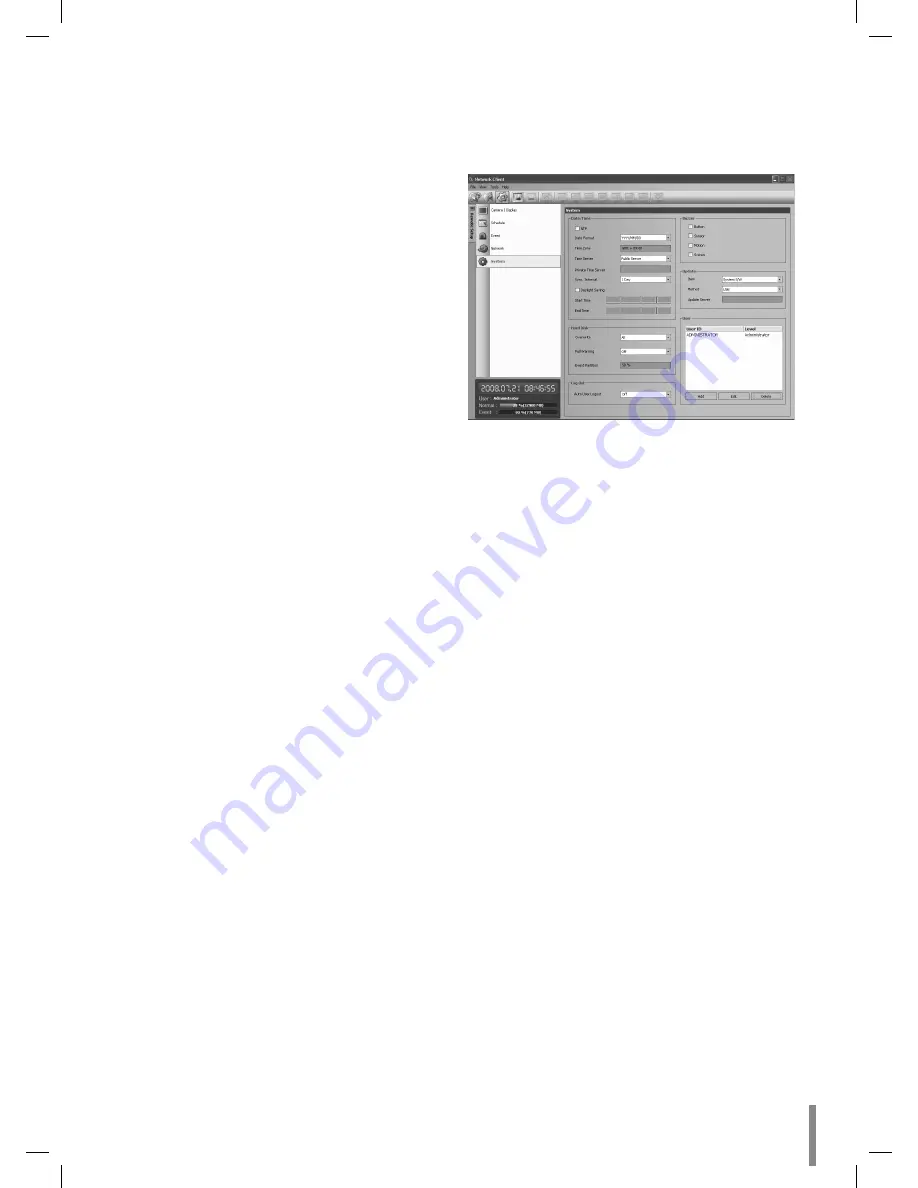
System setup

Date/Time settings

Set the date/time options.

NTP: Mark up when using the NTP (Network Time 
Protocol) server for time adjustment.

Date Format: Select the date display format.

Time Zone: This option setting is not available in the cli-
ent program.

Time Server: Select your time server.
The DVR will obtain the average time among 5 public 
servers (time.nist.gov, time-a.nist.gov, time-b.nist.gov, 
ntp.nasa.gov, clock.isc.org).

Private Time Server: Enter the private time server's IP 
address or host name.

Sync. Interval: You can set synchronized interval with 
the NTP time server to 1 day, 1 hour, 1 week and 1 
month.

Daylight Saving: Mark up when you use the daylight 
saving function.

Start Time: Select the Daylight Saving start time.

End Time: Select the Daylight Saving end time.

Hard disk

Overwrite: Select the overwrite recording type (Off, 
Normal Partition, Event Partition or All). This func-
tion is possible when the selected HDD type has fully 
recorded.

Full Warning: When the HDD has overflowed the warn-
ing message is displayed.

Event Partition: Sets the space of event partitions for 
event recording. 

Log Out

Auto User Logout: Setting the logout time. You can set 
the auto logout time to Off, 5 minutes, 10 minutes, 30 
minutes or 60 minutes.

-

-

Summary of Contents for LE2104

Page 1: ...Before connecting operating or adjusting this product please read this owner s manual carefully and completely DIGITAL VIDEO RECORDER OWNER S MANUAL MODEL LE2104 LE2104D ...

Page 2: ...or glands shall be provided in the cable entries of this product in the end user Caution Danger of explosion if battery is incorrectly replaced Replaced only with the same or equivalent type recommended by the manufacturer Dispose of used batteries according to the manufacturer s instruc tions Holes in metal through which insulated wires pass shall have smooth well rounded surfaces or shall be pro...

Page 3: ...tions 8 Do not install near any heat sources such as radia tors heat registers stoves or other apparatus including amplifiers that produce heat 9 Do not defeat the safety purpose of the polarized or grounding type plug A polarized plug has two blades with one wider than the other A grounding type plug has two blades and a third grounding prong The wide blade or the third prong are provid ed for yo...

Page 4: ...r cable or an unstable surface If you encounter any problems ask your dealer for assistance This may cause fire or electric shock Keep a distance of at least 15cm between the back of the system and the wall for the cables connected to the system otherwise they may be bent damaged or cut This may cause fire electric shock or injury Install the system in a cool place without direct sunlight and alwa...

Page 5: ...e system in a place with magnetic objects electric frequencies or vibration Do not place any heavy object on the system This may cause system breakdown Install the system on a stable level surface The system may not operate properly Install the system in a place with appropriate moisture and temperature levels Avoid installing the system in a place with high over 40 C or low under 0 C temperature ...

Page 6: ... of the LiveScreen on the Main Monitor 18 Configuration menu 22 Camera settings 23 Schedule settings 26 Display settings 29 Event Settings 30 Network Settings 31 System Settings 34 Recording 40 Instant recording 40 Search and Playback 41 Playback 41 Search 41 Client program 44 PC Requirements 44 Client Program Installation 44 Connecting to the DVR 44 Main Screen of DVR Client Program 45 Live Mode ...

Page 7: ...vent data protection by event partition recording Pre alarm recording Up to 1minute Motion event recording Recording image rate quality adjustment per indi vidual camera Powerful record scheduling Instant playback in surveillance mode Perfect audio video synchronization Automatic backup by schedule Image authentication Watermark Three USB 2 0 ports for backup interface Setup configuration export i...

Page 8: ... Search the recorded images in reverse bB Playback or reverse playback of recorded images M Forward search the recorded images x Stops playback f PTZ Switches this unit to PTZ mode to control the PTZ camera connected g COPY Copies the recording data to an external device h LOCK Displays the lock menu to change the user type or disable the system operation i SPLIT Press to see different multiscreen...

Page 9: ... e LAN Port Connect the ethernet 10 100Mbps network cable for controlling this unit via a PC network f TV or VGA output select switch This swith is optional by models g RS 485 Terminals Connect RS 485 compatible cameras Connect the LKD1000 controller to D2 terminal h ALARM IN OUT Terminals IN Input terminals for alarm relay signal OUT Output terminals for alarm relay signal i Power Cord Inlet DC 1...

Page 10: ...elections COPY Copies the recording data to an external device SEARCH Displays the search menu MARK Sets the mark point for recording search You can set the mark point during the single or multi chan nel playback of recorded data PAUSE X Pauses playback STOP x Stops playback REC z Starts or stops recording m c Searches the recorded images in reverse or skips the recorded images bB Playback or reve...

Page 11: ...amera before installation and connection Basic Connection Overview Connect audio line input Connect PTZ cameras DVRs or keypads optional Connect BNC type spot monitor Connect BNC type monitor Connect the alarm relay Connect the coaxial type cameras For audio amplifier Connect power code Connect an external USB device for backup or playback Connect VGA monitor Connect the Monitor DVR VCR or others ...

Page 12: ... simultaneously from the VGA and MAIN OUT jack On other LE2104 LE2104D models with TV VGA output select switch main monitor type should be selected to display the main screen CCTV Composite Video Type Monitor con nection When using the analog TV monitor set the Video Output mode select switch to TV position Connect the unit to the monitors via 75 ohm video coaxial cables with BNC connectors VGA Mo...

Page 13: ...d moni toring work LAN connection Connect the LAN port to an available 10 100 base T port with a straight ethernet cable not supplied The NET indi cator on the front panel will be lit Automatic network configuration The DVR can automatically obtain and configure the net work interface via DHCP Manually configure network The DVR may be manually configured by assigning an IP address subnet mask gate...

Page 14: ...he alarm devices such as sensors door switches etc Alarm Input You can connect up to 4 alarm sensors Each alarm sensor should be connected with G GND The signal state is adjustable to N O Normal Open or N C Normal Close through the setup menu Alarm sensor Rear of the DVR Alarm sensor Terminal No Description 1 Alarm Input 1 2 Alarm Input 2 3 Alarm Input 3 4 Alarm Input 4 G Ground Alarm Output Conne...

Page 15: ...ttached Then add replace or transport the HDD The HDD is very delicate Handle the HDD with care and follow the precautions below because even a small shock may damage the internal components of the HDD Do not place the HDD on a desk or a table directly Put a thick cushion under the HDD because even a small shock may damage the internal components of the HDD Do not use an electric screwdriver Vibra...

Page 16: ...ge the position of the HDD It may delete the current data and cause a mal function Replacing the Hard Disk Drive Turn the power of the unit off and detach the power plug from the outlet 1 Follow steps 1 4 described in Installing the Hard Disk Drive 2 Remove the connector from the HDD 3 Remove the screws from the hard disk drive on the bot tom of the hard disk mounting bracket 4 Remove the HDD from...

Page 17: ...able 3 Enter the password by using the virtual keyboard Initial password is 000000 4 Select OK button and press ENTER You can see the live screen and operate the system Notes The LE2104 LE2104D series models with TV VGA out put select switch can not be outputted simultaneously from the VGA and MAIN OUT jack Consequently the user is obliged to choose either the composite monitor or the VGA monitor ...

Page 18: ...setup menu Displays the search menu Displays the PTZ remote control window Displays in the full screen display mode to return to the 4 division screen windows Views the all channels in sequence on the full screen display mode You cannot use sequence mode with the 4 split Displays the lock menu to change the user type or disable system operation Turns the alarm off Displays the system log list win ...

Page 19: ... displays the setup menu of the PTZ cam era Preset Settings Preset position is the function to register camera monitor ing positions preset positions associated with position numbers By entering the position numbers you can move cameras to the preset positions Note To activate this function you need to register the preset positions of the PTZ cameras To Register Preset Positions 1 Move the camera ...

Page 20: ...ick the icon The setup menu appears in the selected window of the main monitor 2 Use and buttons to set the options Notes Refer to the manuals of the PTZ camera for more details Some PTZ cameras may not operated correctly with this unit You cannot control the other functions when the PTZ virtual remote control is displayed Viewing System Information To view system information 1 Press INFO or click...

Page 21: ... external USB memory device has to be formatted on this unit 1 Connect the USB memory device to the USB port on the front or the rear of the DVR 2 Select the Erase icon then press ENTER Confirm window is displayed after format is com pleted 3 Select OK and press ENTER to close the window Check the size of the selected data and free space of the external device If the device has not enough space cr...

Page 22: ... value Displays the sub setup menu in the live screen mode 1 Click the icon on the bottom of the on screen display with the left mouse button to display a setup menu 2 Click the desired option with the left mouse button to move to the second or third menu level 3 Click the desired option with the left mouse button 4 Set the selected options value 5 Click the icon repeatedly to exit setup menu If t...

Page 23: ...l Selects the desired channel to set the options Name Enter the channel name using up to 12 charac ters b B v V Use to move the columns OK or Cancel button Select a character ENTER Confirms your selection Select OK and press ENTER to save the channel name Select Cancel and press ENTER to exit the virtual keyboard menu Covert You can set the camera conditions to prevent operation by other users If ...

Page 24: ... 19200 Recording Settings concerning normal recording Channel Selects the desired channel to set the options Resolution Selects the recording resolution Quality Selects the recording picture quality LOWEST LOW STANDARD HIGH or HIGHEST Frame Rate Selects the frame rate The frame rate is the number of recorded frames per second According to resolution the frame rate is set automatically If you wish ...

Page 25: ...5 20 30 704 240 1 3 5 7 5 15 704 480 1 3 5 7 5 PAL 352 288 1 3 5 6 12 5 20 25 704 288 1 3 5 6 12 5 704 576 1 3 5 6 Motion Recording Settings concerning motion recording Channel Selects the desired channel to set the options Resolution Selects the recording resolution Quality Selects the recording picture quality LOWEST LOW STANDARD HIGH or HIGHEST Frame Rate Selects the frame rate The frame rate i...

Page 26: ...press ENTER 5 Use b B to adjust the value Brightness Adjust the brightness value from 01 to 100 for the selected channel Contrast Adjust the contrast value from 01 to 100 for the selected channel Color Adjust the color value from 01 to 100 for the selected channel 6 Select OK icon and press ENTER to confirm your set tings 7 Select Exit and press ENTER to exit the sub setup menu Note This function ...

Page 27: ...ording starts automatically Green Blue Continuous Motion event recording Recording starts automatically from the preset time When the motion is detected within a designated time change the continuous recording mode to motion event recording mode and recording starts automatically Green Yellow Continuous Sensor Motion event recording Recording starts automatically from the preset time When the sens...

Page 28: ...dit icon then press ENTER to edit the spe cial day or select the Delete icon to delete the special day schedule 5 Press SETUP ESC to exit the special day schedule list Note If the special day recording schedule is duplicated with the other recordings only the special day recording is possible Copying the Recording Schedule Copying from the Scheduled Data of the Channel You can copy the schedule da...

Page 29: ...is played OFF Remove the current channel recording status Main Monitor Dwell Time You can set the channel sequence time to 2 SEC 5 SEC 10 SEC 20 SEC 30 SEC 40 SEC 50 SEC 60 SEC 70 SEC 80 SEC or 90 SEC Spot Monitor Dwell Time You can set the channel sequence time to 2 SEC 5 SEC 10 SEC 20 SEC 30 SEC 40 SEC 50 SEC 60 SEC 70 SEC 80 SEC or 90 SEC Event Popup Displays an event popup on the spot monitor ...

Page 30: ...n the condition that illumination is low and the outline of object is not clear enough to see regardless of sen sitivity Motion Event could be possible not to happen You must check Motion Event before setting Motion area setting 1 Select the desired channel in live screen mode 2 Press OSD or click the right mouse button to display the sub setup menu 3 Select Motion option and press ENTER 4 Select ...

Page 31: ...ary DNS Enter the Main DNS server address using the virtual keyboard Secondary DNS Enter the Sub DNS server address using the virtual keyboard TCP IP Port Enter the TCP IP Port number using the virtual keyboard You can watch the live surveillance image over the network with the PC Client program The factory default port for transmission of video and audio data is 9001 However in some cases it is b...

Page 32: ... this function How to register DDNS host name With the DDNS function you can easily use LG DVR When you use the DDNS function for the first time after you purchased LG DVR 1 Displays the DVR setup menu 2 Select Network DDNS option 3 Set the DDNS Service to ON 4 Enter the host name in Host Name option 5 Select the Update icon and press ENTER If host registration is properly completed the host name ...

Page 33: ...er option is empty the SMTP Port User Name Password and TLS options are not set SMTP Port Enter the SMTP Port Number using the virtual keyboard Typically the port used for SMTP is 25 However in some cases it is better to change this port number for added flexibility or security If desired change the port number 1 65535 User Name Enter the user name using the virtual key board Password Enter the pa...

Page 34: ...gency agent program using the virtual keyboard The factory default port for this function is 9002 However in some cases it is better to change this port number for added flexibil ity or security If desired change the port number 1025 65535 You can set up to 9 IP port numbers System Settings Date Time Date Enter the current date Time Enter the current time 24 HR or 12 HR Date Format Select the date...

Page 35: ...gov time a nist gov time b nist gov ntp nasa gov clock isc org Private Time Server Enter the private time server s IP address or host name using the virtual keyboard Sync Interval You can set synchronized intervals with the NTP time server to 1 day 1 hour 1 month and 1 week NTP Test Select NTP Test to test the NTP server Buzzer Button ON Makes a sound when using the buttons OFF Turns off the butto...

Page 36: ...date process 1 Select one of the following Select SYSTEM S W to upgrade DVR system soft ware Select PTZ PROTOCOL to update the DVR protocols 2 Choose the media from which to perform the update USB Select USB and then insert the USB drive into the DVR All USB devices must be disconnected before you can use the USB drive NETWORK Select NETWORK and then do following 1 Select the update server setting...

Page 37: ... 40 DAYS 50 DAYS or 60 DAYS If you set the auto delete date the recorded data will be deleted except the data within the selected date period of time The Auto Delete func tion is activated every 35 minutes Note If you change the value of event partition the current recorded data of HDD is deleted and the partition is reset The partitions will be formatted automatically and the system will be resta...

Page 38: ... backup the backup status will be displayed as shown below 1st Status of making ISO image 2nd Status of writing Daily Weekly backup 1 Connect the USB device for backup You cannot use the CD or DVD writer for daily or weekly backup 2 Select WEEKLY or DAILY on the schedule options 3 Select the backup device 4 Enter the date and or time to start backup on the schedule start option 5 Enter the day of ...

Page 39: ...y at fixed inter vals You can set auto logout time to 5 MIN 10 MIN 30 MIN 60 MIN or OFF Default You can reset the DVR to its original factory settings Some options cannot be reset date time day light saving time zone and user password settings Export Export the configuration data from this DVR to the USB memory stick Import Import the DVRs configuration data from the USB memory stick Notes Configu...

Page 40: ...rm motion or continuous Once you stop instant recording the recording type indicator will be changed to the scheduled recording mode You can not record the Instant and Continuous record ing in following conditions A HDD is not attached A HDD is not formatted The channel has no video input for display Overwrite sets to OFF or EVENT PARTITION and normal partition is full On the HDD setting the event...

Page 41: ... SEARCH button is pressed the search menu is displayed Date Time Search Use to search recorded pictures by specifying date and time 1 Use v V to select the Date Time Search option then press ENTER 2 Select Target Device then press ENTER 3 Use b B to select the desired source device INTERNAL HDD Plays back or searches recorded contents of the internal HDD device Source Device Plays back or searches...

Page 42: ...et Device then press ENTER 3 Use b B to select the desired source device 4 Press ENTER to confirm it 5 Select Date option then press ENTER 6 Set the year month or day 6 1 Use b B to select a column and press ENTER 6 2 Use b B to select the year month or day 6 3 Press ENTER to confirm it 6 4 Select OK and press ENTER to confirm the sat tings and exit the date setup menu 7 Select Time option then pr...

Page 43: ...multi channel play back If the storage spaces for bookmark is in full you can not register a bookmark You can register a bookmark after deleting the the previously stored bookmark on the list Functions available during playback Button Function System Control Bar Remote Control Front panel Stop playback Pause playback Press repeatedly to select the required scan speed M MB MM MMB or m mb mm mmb Pre...

Page 44: ...the InstallShield Wizard displayed 3 After installation finished you will find the programs in the start menu of the computer Note The Emergency Agent and Export viewer programs will be installed with the client program installation Connecting to the DVR Register the Site Name You should register a site name to control DVR by the Client Program 1 Double Click the LG Network Client icon to start th...

Page 45: ...twork Client main window is displayed Notes If someone logged in the DVR using the Admin ID you can not log in using the Admin ID If you want to log out right click the mouse on the site name and select User Log Out Up to 5 users can connect to the DVR system using the client program as shown below User User 1 User2 User3 User4 User5 Case 1 Admin Power Normal Normal Normal Case 2 Power Power Norma...

Page 46: ...activated You can print the paused picture of the recorded data of the selected channel 5 Screen Mode Selection Icons Full screen mode You can view the live window s in full screen mode To return to the normal screen right click the mouse Split mode When the icon is clicked the screen will be changed to split mode and if the icon is clicked again the screen will be changed by sequence Choose the d...

Page 47: ...tep 4 Select playback speed D 5 Start playback using these control buttons E Notes If you don t want to play with sound click the speaker icon to mute You can not use the playback function when you log in with the Normal User ID Using the Pan Tilt Zoom Function You can control the PTZ cameras via the network 1 Select Pan Tilt Zoom tab 2 Select the PTZ camera channel window 3 Use virtual remote con...

Page 48: ... 1 Click the icon 2 Use number icons to enter the memorized preset posi tion s index number then Click the icon The camera moves to the preset position and the picture of the camera in that position appears on the monitor To Clear the Preset Position You can delete a memorized preset position 1 Click the icon 2 Use number icons to enter the memorized preset index number then Click the icon The pre...

Page 49: ...k control buttons Using the Event Search function Search a recorded picture by date and event type 1 Select the event search tab 2 Click the date icon and select the day The selectable days are displayed in blue color 3 Select the camera channel for event search 4 Select the event type 5 Select the start time using the timeline 6 Click the search icon The event list is displayed 7 Select the event...

Page 50: ...vity level for the created motion detection area Sensitivity can be set from 0 to 10 Relay Output Select the number of the RELAY OUT terminal for the output alarm signal when motion is detected Area The factory default of the Motion detec tion area is set as the whole area You can change the area by using mouse on the preview window screen Select area Click one point with the left mouse button and...

Page 51: ...in a designated time Continuous Sensor Recording starts automatically from the preset time When the sensor alarm occurs within a designated time change the continuous recording mode to sensor event recording mode and recording starts automatically Continuous Motion Recording starts automatically from the preset time When the motion is detected within a designated time change the continuous recordi...

Page 52: ...add the special day settings The special day is added to the list If you want to cancel the registered special day select the special day in the list and click the delete button Event setup 1 Set the event options Sensor Displays the number of the ALARM IN ter minal Sensor Type The alarm state can be set to either N O Normally Open or N C Normally Closed Linked Camera Select the connected camera c...

Page 53: ...as changed DDNS Host Name The registered host name is displayed Emergency Notification Notify the emergency agent about unit operating information according to your notification settings IP Address Port Enter the IP Address and port num ber of the emergency agent program installed in the PC The factory default port for this function is 9002 However in some cases it is better to change this port nu...

Page 54: ...lete the registered User 1 Choose the user ID you want to delete 2 Click the Delete button Remote Export Settings You can copy the recorded images and audio data from the DVR unit to the PC This function is permitted for Administrator and Power user Export setting Server Displays the selected server name Channel Channel Select a channel s to export the data You should select more than one channel ...

Page 55: ... will be displayed on the Status col umn Note The exported data file name is made automatically as the Server name_Channel number_export start time exp or avi type If you do not assign the export directory the export directory will be set to default directory and sub direc tory will be created with start date If you log out from the network client the export sequence will be terminated You should ...

Page 56: ... the sys tem tray and select the Check Message Box option to display the Received Messages window 5 You can check all the subjects of received messages 6 Click the CLOSE button to close the Received Messages window Main Screen of Emergency Agent a b c d e f g h i a Displays message type b Displays IP Address c Displays received time d Displays the port change window e Displays the search window f ...

Page 57: ...t program or export the data Main Screen of Export Viewer Program Menu File F Open Open the data file Print Prints the current playback image Exit Exit the program Lang L Select the language for Export Viewer pro gram Help H About Export Viewer Displays Export Viewer information Control Icons Jumps to the beginning of the file Pauses playback N Starts playback x Stops playback Jumps to the end of ...

Page 58: ...ted data is played back automatically 5 Click the x STOP button to stop playback Web Viewer Program Logging in the Web Viewer 1 Start the web browser 2 In the Address Box enter HTTP and the IP Address of the DVR You can use the hostname of the No IP web site to connect the DVR 3 Press ENTER and then the Web viewer and the Remote Login menu will be displayed 4 Enter the User Type and Password 5 Cli...

Page 59: ...e channel If you want to set the 1 split mode double click the selected channel To return to the normal screen double click again Right mouse button If you want to exit the full screen mode right click the mouse to return to the normal screen PTZ View control 1 Click the PTZ View icon to change the PTZ view mode The PTZ virtual remote control is displayed 2 Use virtual remote control buttons to co...

Page 60: ...heck the power cable on the camera is connected correctly Check there is no problem with the video cable connection from the camera to the LG DVR system Turn off the DVR system and turn it on again The camera video is shown on the screen but the system does not record the video Check the recording mode in the record setting menu Check the HDD detection status in the System Information window If th...

Page 61: ...camera has a problem Ensure the camera is not damaged by trying another camera with a working video output Check if the video cable connection between the camera and the DVR is cut cross wired or shorted Check if there is a high voltage wire around the video cable connection between cam era and DVR system It can cause interference and affect video quality Check the video cable connection between t...

Page 62: ...blic SMTP server E mail reception failed even if the SMTP server was set When the Please check the SMTP information or internet cable message is dis played Check the SMTP server address Check the SMTP port number Default setting is 25 Check the network settings When the Please check the authentication information message is displayed Check the user name Check the password The mail reception failed...

Page 63: ... O O O O O O Note 8 cm 1 4GB Mini CD DVD and the Dual Layer type media DVD are not supported Supported function list for device Device Instant backup Schedule backup Export Configuration Import Export CD DVD O X O X USB memory O O O O USB HDD O O O O Note If you use a USB memory stick or USB HDD for configuration import export you must disconnect the other external USB devices Supported PTZ Camera...

Page 64: ...me Stockholm Vienna West Central Africa AMS 01 00 02 00 Athens Istanbul Minsk AIM 02 00 03 00 Bucharest Cairo Pretoria Jerusalem Harare Pretoria BCP 02 00 03 00 Helsinki Riga Israel Kyiv Sofia Tallinn Vilnius HRI 02 00 03 00 Baghdad Kuwait Riyadh Nairobi BKR 03 00 04 00 Moscow St Petersburg Volgograd MSV 03 00 04 00 Tehran THE 03 30 04 30 Abu Dhabi Muscat Baku Tbilisi Yerevan ABT 04 00 Kabul KAB 0...

Page 65: ...SEC Sensor Recording Channel CH 01 CH 04 Resolution 352X240 NTSC 352X288 PAL Quality STANDARD Frame rate 30 NTSC 25 PAL Motion Recording Channel CH 01 CH 04 Resolution 352X240 NTSC 352X288 PAL Quality STANDARD Frame rate 30 NTSC 25 PAL Video Format Video Format NTSC or PAL Schedule Sunday Sensor Motion Monday Sensor Motion Tuesday Sensor Motion Wednseday Sensor Motion Thursday Sensor Motion Friday...

Page 66: ...ULL Primary DNS NULL Secondary DNS NULL TCP IP Port 9001 Web Server Port 80 Bandwidth Throttle 100 Mbps DDNS DDNS Service OFF Host Name NULL Registered Host NULL Update Notification Sensor On OFF Motion Detection OFF Disk Full OFF Admin PWD Changed OFF Video Loss OFF Power On Off OFF Mail Notification OFF SMTP Server NULL SMTP Port 25 User Name NULL Password NULL TLS OFF Mail Address 1 NULL Mail A...

Page 67: ...Interval 1 DAY NTP Test Buzzer Button OFF Sensor OFF Motion OFF System OFF User Number ID ADMINISTRATOR Level Administrator Password 000000 Update Item SYSTEM S W Method USB Update Server NULL Update Hard Disk Format Overwrite ALL Full Warning 70 Event Partition 50 Auto Delete OFF Backup Partition Selection ALL Schedule OFF Device Schedule Start Current Time Time Range Date Current Time Time Range...

Page 68: ...1493 1044 12 5 1123 848 7 5 1975 1259 6 1577 1084 5 1960 1253 5 1846 1205 3 2064 1295 3 1938 1244 1 2196 1345 1 2011 1274 Normal 30 1038 799 25 703 585 20 1182 882 20 686 573 15 1131 853 12 5 768 629 7 5 1496 1045 6 1175 878 5 1458 1027 5 1256 922 3 1529 1061 3 1262 926 1 1604 1097 1 1374 984 High 30 780 637 25 517 450 20 916 725 20 495 434 15 897 713 12 5 560 482 7 5 1211 898 6 949 746 5 1191 887...

Page 69: ... 1907 1231 Low 15 939 739 12 5 734 606 7 5 1164 872 6 934 736 5 1186 884 5 1080 824 3 1414 1005 3 1213 899 1 1355 975 1 1233 910 Normal 15 770 630 12 5 584 500 7 5 913 723 6 607 517 5 911 721 5 654 550 3 930 734 3 692 577 1 993 772 1 927 732 High 15 627 531 12 5 454 401 7 5 754 620 6 474 417 5 755 620 5 523 455 3 775 634 3 571 490 1 825 667 1 767 628 Best 15 574 493 12 5 381 344 7 5 683 571 6 401 ...

Page 70: ...00 3 944 742 3 799 650 1 1093 831 1 1072 819 Low 7 5 651 548 6 473 417 5 672 563 5 607 516 3 737 608 3 655 551 1 833 672 1 811 658 Normal 7 5 598 511 6 407 365 5 605 515 5 551 476 3 655 551 3 589 504 1 712 591 1 675 565 High 7 5 518 450 6 349 317 5 518 451 5 477 419 3 557 480 3 506 442 1 606 516 1 568 488 Best 7 5 476 419 6 279 258 5 477 419 5 410 366 3 509 444 3 437 388 1 552 477 1 494 432 ...

Page 71: ...ding Yes Pre Event Recording Time Up to 60 sec Search Playback Function FF FB Frame Advance Playback Speed x1 x2 x4 x8 x16 x1 x2 x4 x8 x16 Search Mode Date Time Event Motion Alarm Boorkmark Instant Playback Yes Display User I F Screen Division Mode 1 4 OSD type GUI User Interface Mouse IR Remote Keyboard Controller LKD1000 Storage Interanl HDD Interface Type SATA Max Capacity 1TB Up to 2 HDDs LE21...

Page 72: ... System Multiplex Triplex Setup Configuration Export Import USB Memory Stick Network Daylight Saving Yes Auto Delete Data Retension Yes Dome Camera Telemetry Control Yes S W Update Interface USB Memory Network Update Item PTZ Firmware General Video Codec H 264 Power Source DC 12V 5A Adaptor AC100 240V 50 60 Hz Power Consumption 40W Max with HDD x 2 Dimension WxDxH mm 430 x 316 8 x 54 Weight 2 7Kg ...

Reviews: