Jam access area
Printer control panel message
What to do
3
Front door
[x]
‑
page jam, open front
door. [20y.xx]
Open the front door, then remove the toner cartridge and
imaging unit, and then the jammed paper.
4
Multipurpose
feeder
[x]
‑
page jam, clear manual
feeder. [25y.xx]
Remove all paper from the multipurpose feeder, and then
remove the jammed paper.
5
Tray 1
[x]
‑
page jam, remove tray 1 to
clear duplex. [23y.xx]
Pull out tray 1 completely, then push the front duplex flap
down, and then remove the jammed paper.
Note:
You may need to open the rear door to clear
some 23y.xx paper jams.
6
Tray [x]
[x]
‑
page jam, open tray
[x]. [24y.xx]
Pull the indicated tray out, and then remove the jammed
paper.
7
Rear door
[x]
‑
page jam, open rear
door. [20y.xx]
Open the rear door, and then remove the jammed paper.
8
Finisher rear door
[x]-page jam, remove all pages
from the finisher’s accumulator.
Leave paper in bin [45y.xx]
•
Open the finisher rear door, and then remove the
jammed paper.
•
Open the trap door, and then remove the jammed
paper.
9
Finisher output bin
[x]-page jam, remove all pages
from the output bin. Leave paper
in bin [45y.xx]
•
Move the left tamper arm to the left and the right
tamper arm to the right, and then remove the jammed
paper from the finisher bin.
•
Open the finisher rear door and the trap door, and
then remove any jammed pages.
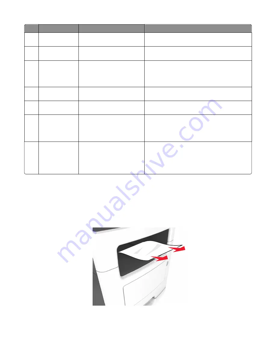
200 paper jams
[x]
‑
page jam, clear standard bin. [20y.xx]
1
Firmly grasp the jammed paper on each side, and then gently pull it out.
Note:
Make sure all paper fragments are removed.
2
From the printer control panel, touch
Done
to clear the message and continue printing.
7016
Diagnostic information
48
Summary of Contents for 7016-630
Page 14: ...7016 Table of contents 14 ...
Page 22: ...7016 22 ...
Page 24: ...7016 24 ...
Page 34: ...7016 34 ...
Page 160: ...7016 160 ...
Page 184: ...D ADF cover open E Flatbed cover open F Paperfeed sensor 7016 Service menus 184 ...
Page 200: ...7016 200 ...
Page 240: ...5 Remove the screw A from the rear side of the printer 7016 Repair information 240 ...
Page 249: ...4 Remove the four screws B and then remove the right front mount 7016 Repair information 249 ...
Page 332: ...4 Remove the screw D 5 Disconnect the spring E 7016 Repair information 332 ...
Page 337: ...Remove the screw A then remove the cover 7016 Repair information 337 ...
Page 352: ...7 Remove the four screws A from the power supply unit 7016 Repair information 352 ...
Page 366: ...7016 366 ...
Page 377: ...Power supply PCN1 PCN2 PCN3 PCN5 PCN4 7016 Component locations 377 ...
Page 378: ...7016 378 ...
Page 383: ...7016 383 ...
Page 385: ...Assembly 1 Covers 1 2 3 4 5 6 15 16 7 12 8 11 10 9 13 14 7016 Parts catalog 385 ...
Page 387: ...Assembly 2 Imaging 1 2 3 4 5 6 7 10 9 8 11 12 13 14 15 16 7016 Parts catalog 387 ...
Page 389: ...Assembly 3 Control panel 1 2 3 4 5 8 7 6 7016 Parts catalog 389 ...
Page 391: ...Assembly 4 Electronics 1 1 2 3 5 7 8 4 6 7016 Parts catalog 391 ...
Page 393: ...Assembly 5 Electronics 2 4 3 2 1 5 6 7 8 7016 Parts catalog 393 ...
Page 395: ...Assembly 6 Frame 3 10 11 12 13 14 9 1 6 5 7 8 15 2 4 7016 Parts catalog 395 ...
Page 397: ...Assembly 7 Option trays 3 4 5 6 1 2 7016 Parts catalog 397 ...
Page 399: ...Assembly 8 Staple finisher option 1 7016 Parts catalog 399 ...
Page 401: ...Assembly 9 Staple finisher right 1 2 3 4 5 6 7 7016 Parts catalog 401 ...
Page 403: ...Assembly 10 Staple finisher top 1 2 3 4 5 6 7016 Parts catalog 403 ...
Page 405: ...Assembly 11 Staple finisher rear 1 2 3 4 5 6 7 7016 Parts catalog 405 ...
Page 408: ...7016 Parts catalog 408 ...
Page 410: ...7016 Parts catalog 410 ...
Page 412: ...7016 412 ...
Page 418: ...7016 418 ...
Page 442: ...7016 Index 442 ...
Page 448: ...7016 Part number index 448 ...
Page 454: ...7016 Part name index 454 ...


