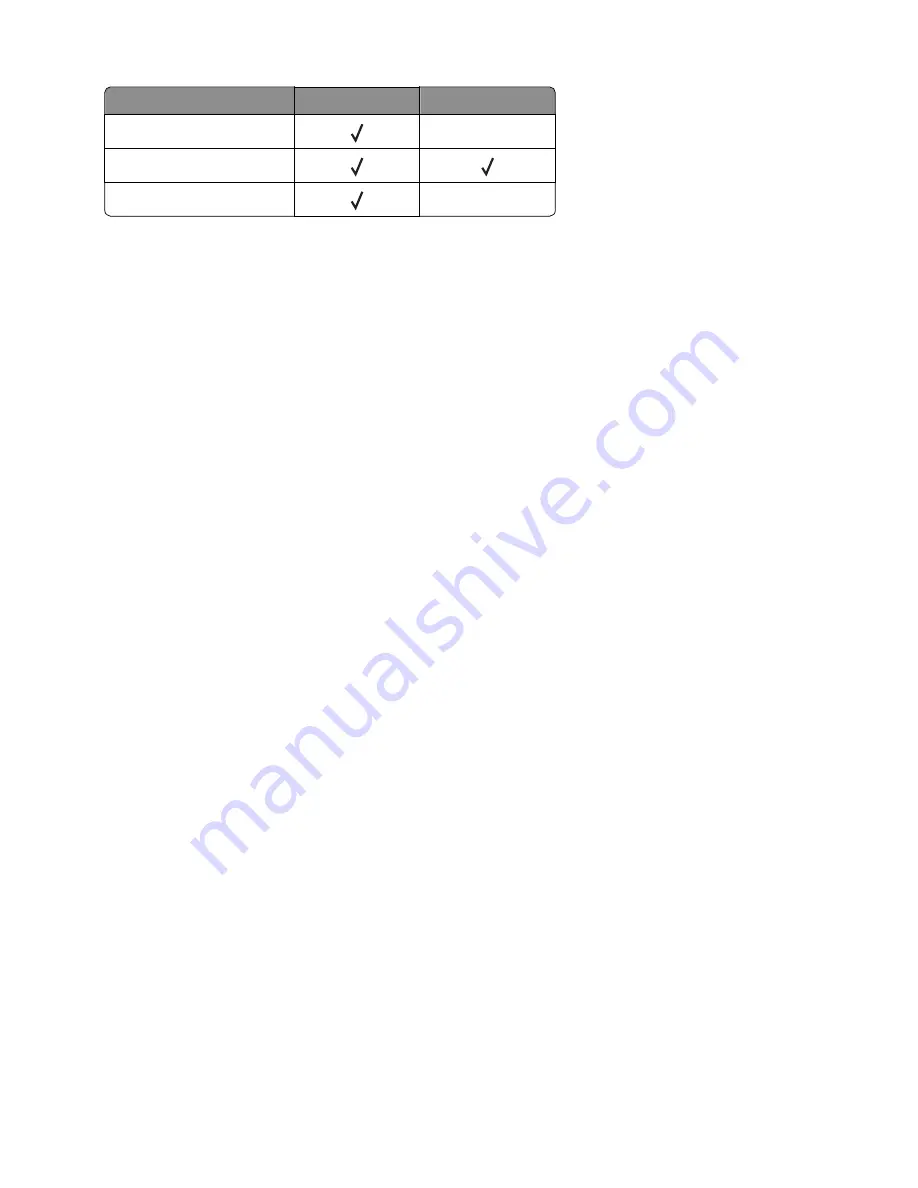
Input source
Tray empty sensor Pass through sensor
Standard tray
Optional 250
‑
/550-sheet tray
Multipurpose feeder
3
Manually actuate each sensor. The tray empty sensor can be actuated by hand; however, a sheet of paper can be
used to cover the pass through sensor.
4
Press
X
to exit the test.
OUTPUT BIN TESTS
Feed Tests
This test verifies that media can be fed to a specific output bin. No information is printed on the media.
To run this test:
1
From the Diagnostics menu, navigate to:
Output Bin Tests
>
Feed Tests
2
Select the output bin into which you want the paper to exit. All installed output bins appear.
3
Select one of the following:
•
Single—Feeds a single page.
•
Continuous—Continuously feeds pages until
X
is pressed.
Sensor Test
This test verifies that the output bin sensors are working correctly.
To run this test:
1
From the Diagnostics menu, navigate to:
Output Bin Tests
>
Sensor Test
>
Standard Bin
Testing...
appears while the printer is verifying the state of the sensor.
The control panel displays the current state of the sensor.
2
Manually actuate the sensor to make it toggle between
empty
and
full
. If the sensor does not toggle, then the
sensor is malfunctioning.
3
Press
X
to exit the test.
BASE SENSOR TEST
Use the Base Sensor Test to determine that the sensors located inside the printer are operating correctly.
The following sensors can be checked using this test:
•
Narrow Media
•
Input
7016
Service menus
174
Summary of Contents for 7016-630
Page 14: ...7016 Table of contents 14 ...
Page 22: ...7016 22 ...
Page 24: ...7016 24 ...
Page 34: ...7016 34 ...
Page 160: ...7016 160 ...
Page 184: ...D ADF cover open E Flatbed cover open F Paperfeed sensor 7016 Service menus 184 ...
Page 200: ...7016 200 ...
Page 240: ...5 Remove the screw A from the rear side of the printer 7016 Repair information 240 ...
Page 249: ...4 Remove the four screws B and then remove the right front mount 7016 Repair information 249 ...
Page 332: ...4 Remove the screw D 5 Disconnect the spring E 7016 Repair information 332 ...
Page 337: ...Remove the screw A then remove the cover 7016 Repair information 337 ...
Page 352: ...7 Remove the four screws A from the power supply unit 7016 Repair information 352 ...
Page 366: ...7016 366 ...
Page 377: ...Power supply PCN1 PCN2 PCN3 PCN5 PCN4 7016 Component locations 377 ...
Page 378: ...7016 378 ...
Page 383: ...7016 383 ...
Page 385: ...Assembly 1 Covers 1 2 3 4 5 6 15 16 7 12 8 11 10 9 13 14 7016 Parts catalog 385 ...
Page 387: ...Assembly 2 Imaging 1 2 3 4 5 6 7 10 9 8 11 12 13 14 15 16 7016 Parts catalog 387 ...
Page 389: ...Assembly 3 Control panel 1 2 3 4 5 8 7 6 7016 Parts catalog 389 ...
Page 391: ...Assembly 4 Electronics 1 1 2 3 5 7 8 4 6 7016 Parts catalog 391 ...
Page 393: ...Assembly 5 Electronics 2 4 3 2 1 5 6 7 8 7016 Parts catalog 393 ...
Page 395: ...Assembly 6 Frame 3 10 11 12 13 14 9 1 6 5 7 8 15 2 4 7016 Parts catalog 395 ...
Page 397: ...Assembly 7 Option trays 3 4 5 6 1 2 7016 Parts catalog 397 ...
Page 399: ...Assembly 8 Staple finisher option 1 7016 Parts catalog 399 ...
Page 401: ...Assembly 9 Staple finisher right 1 2 3 4 5 6 7 7016 Parts catalog 401 ...
Page 403: ...Assembly 10 Staple finisher top 1 2 3 4 5 6 7016 Parts catalog 403 ...
Page 405: ...Assembly 11 Staple finisher rear 1 2 3 4 5 6 7 7016 Parts catalog 405 ...
Page 408: ...7016 Parts catalog 408 ...
Page 410: ...7016 Parts catalog 410 ...
Page 412: ...7016 412 ...
Page 418: ...7016 418 ...
Page 442: ...7016 Index 442 ...
Page 448: ...7016 Part number index 448 ...
Page 454: ...7016 Part name index 454 ...


