background image

Function and Commissioning of the TNT 35

38

TNT 35 und TNT 35/7-24V

Leuze electronic

DEUTSCH

E

NGLISH

FRANÇAIS

IT

A

LIANO

ESPAÑOL

N

EDERLANDS

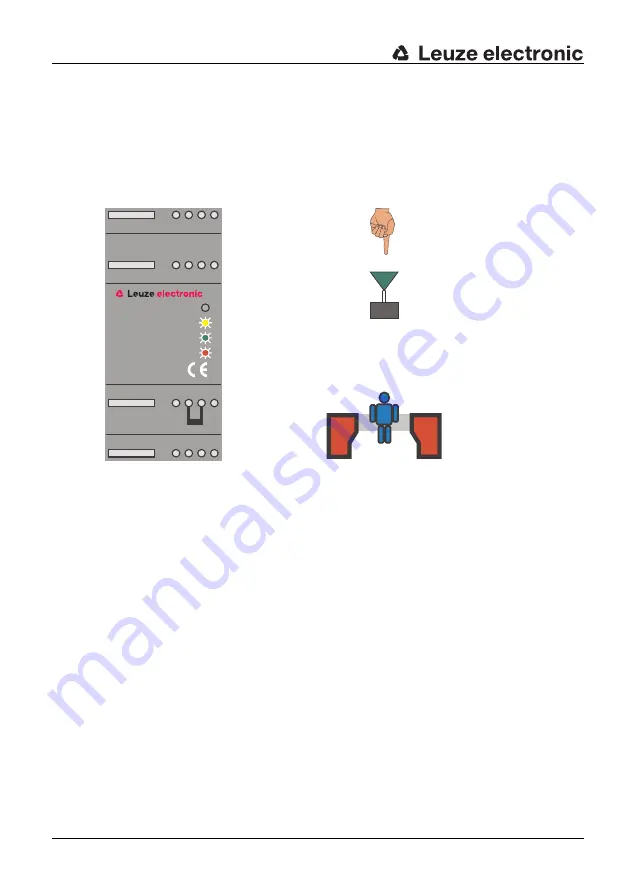
Safety field interruption:

The safety outputs of the TNT 35 are opened (LED "OFF/ON" on red) if during safety 
operation the light beam of the protective photoelectric sensor is interrupted.

The restart-disable inside the TNT 35 becomes active and prevents an automatic restart of 
the machine. The yellow LED "Start" displays the function of the restart-disable.
The TNT 35 is in waiting state and can be restarted by pressing the start-/restart button 
after the safety field is free.

4.6

Fault indication and device reset

Faults of the test monitoring unit TNT 35 are indicated by the blinking of the red "ON/OFF" 
LED. The possible faults are:

Fault in the operating mode selection:

The selected operating mode of the device at startup (with/without start- and restart-
disable) changed during operation. The jumper (terminal 22 to terminal 23 or terminal 23 to 
terminal 24) should be checked that it is set to the desired operating mode.

Fault in the relay monitoring:

A fault in the wiring or soldered safety contacts was detected by the TNT 35. The wiring 
and connected contacts should be checked.

Internal device failures:

Equipment faults that are caused by an internal defect result in the unit going into locked 
state. 

Figure 4.5-4:

Display of the TNT 35 during a safety field interruption

5 6

8

7

13 14 15 16

21 22 23 24

29 30 31 32

Sensor

Start/Active

EDM

OFF/ON

TNT35

Start

Activation

SLS

Summary of Contents for TNT 35

Page 1: ...TNT 35 Test monitoring units 607112 2010 11 Subject to change wit hout prior notice C O N N E C T I N G A N D O P E R A T I N G I N S T R U C T I O N S O r i g i n a l I n s t r u c t i o n s...

Page 2: ...symbol Notes regarding important pieces of information are marked by the symbol This connecting and operating instructions manual must be stored carefully It must be available for the entire operatin...

Page 3: ...axle installation 13 4 Function and Commissioning of the TNT 35 15 4 1 Function characteristics of the safety system 15 4 1 1 Display and Operating Instruments 15 4 2 Electrical Installation 16 4 2 1...

Page 4: ...Operating states with start and restart disable without relay monitoring EDM 57 5 5 Operating states with start and restart disable and with relay monitoring EDM 61 5 6 Fault indication and device re...

Page 5: ...e device is part of the electrical equipment which has to be applied to those machines which contain the potential risk of bodily injury They provide protection by causing the machine to move into a s...

Page 6: ...ort into the hazardous area Muting sensors Muting sensors define between persons and transported material If the muting sensors are activated simultaneously or in the intended order the safety functio...

Page 7: ...y field the access points the hazardous areas bypassing possibilities Determination of the protective function Finger and hand protection The user is close to the hazardous area Access protection Acce...

Page 8: ...08 EC Use of Work Equipment Directive 89 655 EEC supplemented by Directive 95 63 EC OSHA 1910 Subpart 0 Safety regulations Accident prevention regulations and safety rules Ordinance on Industrial Safe...

Page 9: ...s may be present at the switching outputs In addition to the power supply these must be switched off and safeguarded against being switched back on prior to all work on the TNT 35 These operating inst...

Page 10: ...t and the machine he has been instructed by the responsible person on the mounting and operation of the machine and of the Test Monitoring Unit 2 3 Responsibility for safety Manufacturer and operating...

Page 11: ...ity Leuze electronic GmbH Co KG is not liable in the following cases Test Monitoring Unit is not used as intended safety notices are not adhered to reasonably foreseeable misuse is not taken into acco...

Page 12: ...way that the dangerous area cannot be reached within this time delay The minimum distance for safeguarding the hazardous area is 850 mm Calculation of the safety distance The safety distance S between...

Page 13: ...to IS0 13855 The number of needed systems results from the corresponding type C standard or risk evaluation Deflection mirrors A number of important factors have to be observed when using deflection...

Page 14: ...tric sensor has to be mounted with a minimum lateral distance to the reflecting surface This distance results from the opening angle 4 and the distance between transmitter and receiver Figure 3 1 3 Ar...

Page 15: ...start disable as well as a selectable relay monitoring input are integrated 4 1 1 Display and Operating Instruments The test monitoring unit TNT 35 features integrated LEDs to indicate the state of th...

Page 16: ...nel Supply and signal lines have to be installed separately from power lines during installation Inside the switching cabinet suitable spark extinction has to be provided if using contactors When inst...

Page 17: ...OL NEDERLANDS 4 2 1 Supply wiring The test monitoring unit TNT 35 is supplied with 24V DC 15 The max current consumption is 200mA The 24V supply voltage is connected to terminal 5 and the GND is conn...

Page 18: ...le and without start and restart disable in different ways In the operating mode with start and restart disable the TNT 35 expects two signal changes push button function as switch on signal A failure...

Page 19: ...without start and restart disable the start input works as activation input As soon as a HIGH active signal is present at the start input terminal 16 and the safety field is free the safety outputs a...

Page 20: ...nnected to terminal 14 on the TNT 35 The switching output of the receiver can be directly connected to terminal 15 The GND potential present on terminal 6 serves as a reference potential for both sign...

Page 21: ...The receiver is activated via the first optical path and by using its output activates the second photoelectric sensor transmitter The supply has to provided on each photoelectric transmitter and rece...

Page 22: ...safety relay outputs are connected in series The release circuit can be connected to further components which are then wired to a common EMERGENCY SHUT DOWN device Note For the operating mode without...

Page 23: ...integrated seperately into the release circuits These circuits can be connected with additional components which trigger a common EMERGENCY SHUT DOWN device Note For the operating mode without relay m...

Page 24: ...uses are included However for correct function fuses are absolutely required The maximum contact load of the safety relay outputs is 4A with 24VDC Control of the motor contactors happens via K1 and K2...

Page 25: ...he safety relay outputs are closed The message output Error is always active if the TNT 35 detects an error Those errors can be internal or external Through linking of the status outputs in the contro...

Page 26: ...r between terminals 22 and 23 or terminals 23 and 24 Warning Terminals 22 23 and 24 may only be used to for selecting the operating mode using the included short circuit jumpers With start and restart...

Page 27: ...nactive by connecting a jumper between terminals 23 and 24 Completing the setting After the setting has been changed the new device setting must be saved This is done either by triggering the Reset in...

Page 28: ...disable Stand by operation The free light path is displayed by the green LED Sensor Activation is not used The safety outputs are open This state is displayed by the red LED The display for the relay...

Page 29: ...e function of the protective photoelectric sensor is cyclically tested every two seconds The free safety field is displayed by the green LED Activation is used green LED The safety output is closed wh...

Page 30: ...ing terminal 13 always must be wired For operation without the relay monitoring function a jumper can be set between terminal 13 and terminal 14 Connected relays can be monitored if the wiring of the...

Page 31: ...ng EDM Stand by operation The free light path is displayed by the green LED Sensor The start input has not been activated The safety output is open This state is displayed by the red LED OFF ON The ye...

Page 32: ...e test monitoring unit is checked To induce the test operation the start input is activated green LED Start As long as the start restart button is pressed the test operation remains active After relea...

Page 33: ...ion the function of the protective photoelectric sensor is cyclically tested every two seconds The free safety field is displayed by the green LED Sensor The safety outputs are closed which is display...

Page 34: ...electric sensor is interrupted The restart disable inside the TNT 35 becomes active and prevents an automatic restart of the machine The yellow LED Start displays the function of the restart disable T...

Page 35: ...DM Stand by operation The free light path is displayed by the green LED Sensor The relay monitoring EDM is active green LED EDM The safety output is open This state is displayed by the red LED OFF ON...

Page 36: ...e test monitoring unit is checked To induce the test operation the start input is activated green LED Start As long as the start restart button is pressed the test operation remains active After relea...

Page 37: ...photoelectric sensor is cyclically tested every two seconds The free safety field is displayed by the green LED Sensor The relay monitoring is inactive in safety operation green LED EDM off The safety...

Page 38: ...s of the test monitoring unit TNT 35 are indicated by the blinking of the red ON OFF LED The possible faults are Fault in the operating mode selection The selected operating mode of the device at star...

Page 39: ...m a locked state is carried out by disconnecting the supply voltage for a short time or by applying a reset signal 24V potential to the reset input terminal 21 The LED will stop blinking after the fau...

Page 40: ...FHd 8 8 x 10 8 1 h Mean time to dangerous failure MTTFd 69 years Degree of cover DC 94 Number of cycles until 10 of the components have a failure to danger B10d DC 13 24 V 10 million switching cycles...

Page 41: ...Safety output voltage free make contact max switching voltage 250V AC max current load 4 A Safeguarding externally with max 4 A slow blow Overvoltage category 2 for rating voltage 300V AC according t...

Page 42: ...voltage free safety relay outputs can be directly used for shut down of the dangerous movement Inside the Test Monitoring unit TNT 35 7 24V a selectable start and restart disable as well as a selecta...

Page 43: ...circuit open or closed 5 2 Electrical Installation Warning The electrical installation is only to be performed by specialised personnel Supply and signal lines have to be installed separately from po...

Page 44: ...onnected safety sensors A supply voltage of 24VDC is available at terminals 5 10 and 11 The corresponding GND potential is available on terminals 2 3 and 6 The maximum current consumption of the safet...

Page 45: ...the operating mode with start and restart disable the TNT 35 7 24V expects two signal changes push button function as switch on signal A failure in the start restart button e g due to contact malfunct...

Page 46: ...ion input As soon as a HIGH active signal is present at the start input terminal 16 and the safety field is free the safety outputs are closed A 24V suppy terminal e g terminals 5 10 or 11 can be used...

Page 47: ...tly connected to terminal 14 on the TNT 35 7 24V The switching output of the receiver can be directly connected to terminal 15 The 24V supply for the safety sensors is taken from the supply terminals...

Page 48: ...s activated via the first optical path and by using its output activates the second photoelectric sensor transmitter The supply has to provided on each photoelectric transmitter and receiver The feedb...

Page 49: ...l release circuit without relay monitoring Two safety relay outputs are connected in series The release circuit can be connected to further components which are then wired to a common EMERGENCY SHUT D...

Page 50: ...ing Both safety relay outputs are integrated seperately into the release circuits These circuits can be connected with additional components which trigger a common EMERGENCY SHUT DOWN device Figure 5...

Page 51: ...nd K2 should fuse together a message is issued to the TNT 35 7 24V through the feedback circuit EDM A new start of the unit is possible only after removal of the failure in the output circuit 5 2 7 Wi...

Page 52: ...r external Warning The message outputs on terminals 17 18 and 19 are only approved for 24V DC operation Do not connect to higher voltages 5 2 8 Setting of the operating mode The start and restart disa...

Page 53: ...Without start and restart disable The start and restart disable is set to inactive by connecting a jumper between terminals 23 and 24 Figure 5 2 10 Operating mode with start and restart disable Figur...

Page 54: ...suppy voltage on and off for a short time 5 3 Operating states without start and restart disable Stand by operation The free light path is displayed by the green LED Sensor Activation is not used The...

Page 55: ...tective photoelectric sensor is cyclically tested every two seconds The free safety field is displayed by the green LED Activation is used green LED The safety output is closed which is displayed by t...

Page 56: ...always must be wired For operation without the relay monitoring function a jumper can be set between terminal 13 and terminal 14 Connected relays can be monitored if the wiring of the input to termina...

Page 57: ...een LED Sensor The start input has not been activated The safety output is open This state is displayed by the red LED OFF ON The yellow LED Start displays the lock of the start and restart disable No...

Page 58: ...activated green LED Start As long as the start restart button is pressed the test operation remains active After release of the start restart button the TNT 35 7 24V changes from test operation to saf...

Page 59: ...the protective photoelectric sensor is cyclically tested every two seconds The free safety field is displayed by the green LED Sensor The safety outputs are closed which is displayed by the green LED...

Page 60: ...rrupted The restart disable inside the TNT 35 7 24V becomes active and prevents an automatic restart of the machine The yellow LED Start displays the function of the restart disable The TNT 35 7 24V i...

Page 61: ...The free light path is displayed by the green LED Sensor The relay monitoring EDM is active green LED EDM The safety output is open This state is displayed by the red LED OFF ON The yellow LED Start...

Page 62: ...s checked To induce the test operation the start input is activated green LED Start As long as the start restart button is pressed the test operation remains active After release of the start restart...

Page 63: ...is cyclically tested every two seconds The free safety field is displayed by the green LED Sensor The relay monitoring is inactive in safety operation green LED EDM off The safety outputs are closed w...

Page 64: ...nitoring unit TNT 35 7 24 are indicated by the blinking of the red ON OFF LED The possible faults are Fault in the operating mode selection The selected operating mode of the device at startup with wi...

Page 65: ...upply voltage for a short time or by applying a reset signal 24V potential to the reset input terminal 21 The 24V potential for the reset signal can be taken from terminals 5 10 or 11 The LED will sto...

Page 66: ...e to danger B10d DC 13 24 V 10 million switching cycles 2 A AC 15 230 V 100 000 switching cycles 2 A 600 000 switching cycles 1 A 1 3 million switching cycles 0 5 A Service life TM 20 years Electrical...

Page 67: ...ng voltage 250V AC max current load 4A Safeguarding externally with max 4 A slow blow Overvoltage category 2 for rating voltage 300V AC according to VDE 0110 part 1 Environmental data Ambient temperat...

Page 68: ...afety sensors comes directly from the power supply of the installation machine Test monitoring of the photoelec tric sensors is carried out by the TNT 35 Figure 6 1 1 Connection diagram for connecting...

Page 69: ...T 35 Retro reflective photoelectric safety sensors Active The operating mode is selected using a jumper between terminal 22 23 with start restart disable or terminal 23 24 without start restart disabl...

Page 70: ...he photoelectric sensors is carried out by the TNT 35 Figure 6 2 1 Connection diagram for a pair of SLS 96s 24 14 32 31 30 29 7 8 6 5 13 23 22 16 21 15 Start Active Reset GND 24V Active TNT 35 Protect...

Page 71: ...photoelec tric barriers is carried out by the TNT 35 Figure 6 3 1 Connection diagram for a pair of ECOs 24 14 32 31 30 29 7 8 6 5 13 23 22 16 21 15 Start Active Reset GND 24V TNT 35 Safety light barri...

Page 72: ...lation machine Test monitoring of the photoelectric barriers is carried out by the TNT 35 Figure 6 4 1 Connection diagram for connecting a ROBUST 22 24 14 32 31 30 29 7 8 6 5 13 23 22 16 21 15 Start A...

Page 73: ...UT DOWN button s can be wired into the voltage supply of the TNT 35 If an EMERGENCY SHUT DOWN situation occurs the TNT 35 will be disconnected from its voltage supply resulting in the outputs switchin...

Page 74: ...nsors is carried out by the TNT 35 7 24 Warning In the above example the start and restart disable function is deactivated The start and restart disable function must be activated or deactivated depen...

Page 75: ...sors is carried out by the TNT 35 7 24 Warning In the above example the start and restart disable function is deactivated The start and restart disable function must be activated or deactivated depend...

Page 76: ...nes are fulfilled if using the shown components and the corresponding wiring Remaining risks are present if the proposed circuit concept is changed and the connected safety relevant components or prot...

Page 77: ...electronic TNT 35 und TNT 35 7 24V 77 TNT 35 7 24V DEUTSCH ENGLISH FRAN AIS ITALIANO ESPA OL NEDERLANDS 8 EC Declaration of Conformity You can download this EC Declaration of Conformity on the Interne...

Reviews: