Note :
• The counter for number of remaining resets is reset
to zero when :
- the cause of the trip disappears before all the reset
attempts have occurred,
- the power is switched on,
- the value of P50 is modified.
• The trip is only registered in the fault log when all the
attempts to reset have been performed without success.
• The external trip " Et " (terminal C7) cannot be reset by
this function.
: Automatic reset delay
Adjustment range : 1 to 5s.
Factory setting
: 1s.
Mnemonic :
RD.
In increments of 0.1s.
Allows adjustment of the time between the trip condition
and its automatic reset.
: Selection of the relay function
Adjustment range : 0 or 1.
Factory setting
: 0.
b50 = 0 : the contact between terminals A1 and A2 is
closed when the inverter is powered up and not tripped.
b50 = 1 : the contact between terminals A1 and A2 is
closed when the output frequency is higher than P0 and
when the inverter is not tripped.
Note : The contact is open when the modulator is
powered down, see section 3.2, relay characteristics.
: Enable the Fwd/Rev key
Adjustment range : 0 or 1.
Factory setting
: 0.
b51 = 0 : the key cannot change the direction of rota-
tion of the motor if b9 = 0.
b51 = 1 : pressing the key changes the direction
of rotation of the motor if b9 = 0.
: Catch spinning motor
Adjustment range : 0 or 1.
Factory setting
: 0.
Mnemonic :
C1-12.
b52 = 0 : the catch spinning motor function is disabled.
b52 = 1 : allows an inverter run command when the
motor shaft is turning.
The inverter searches for the motor frequency from P1 to
0 Hz in both directions of rotation ( " SCN " appears on
the display during this operation). After
synchronisation, the motor accelerates until it reaches
the speed reference. Depending on the dynamic
conditions of the system, this operation may take up to
5 seconds.
CAUTION
- Do not open the line contactor during this
operation.
- Systems without a mechanical load in these
conditions can change speed or turn slowly in both
rotational directions before starting during this
operation.
The search is faster when the forward operation
command is selected. For a single direction of rotation,
use forward operation and cross 2 phases on the motor
side for the required direction.
: Selection of logic output A3
Adjustment range : 0 or 1.
Factory setting
: 0.
Mnemonic :
C1 - C3.
b53 = 0 : logic output A3 = 0V when the inverter receives
a run command.
b53 = 1 : logic output A3 = 0V when the output frequency
is higher than the minimum frequency (P0).
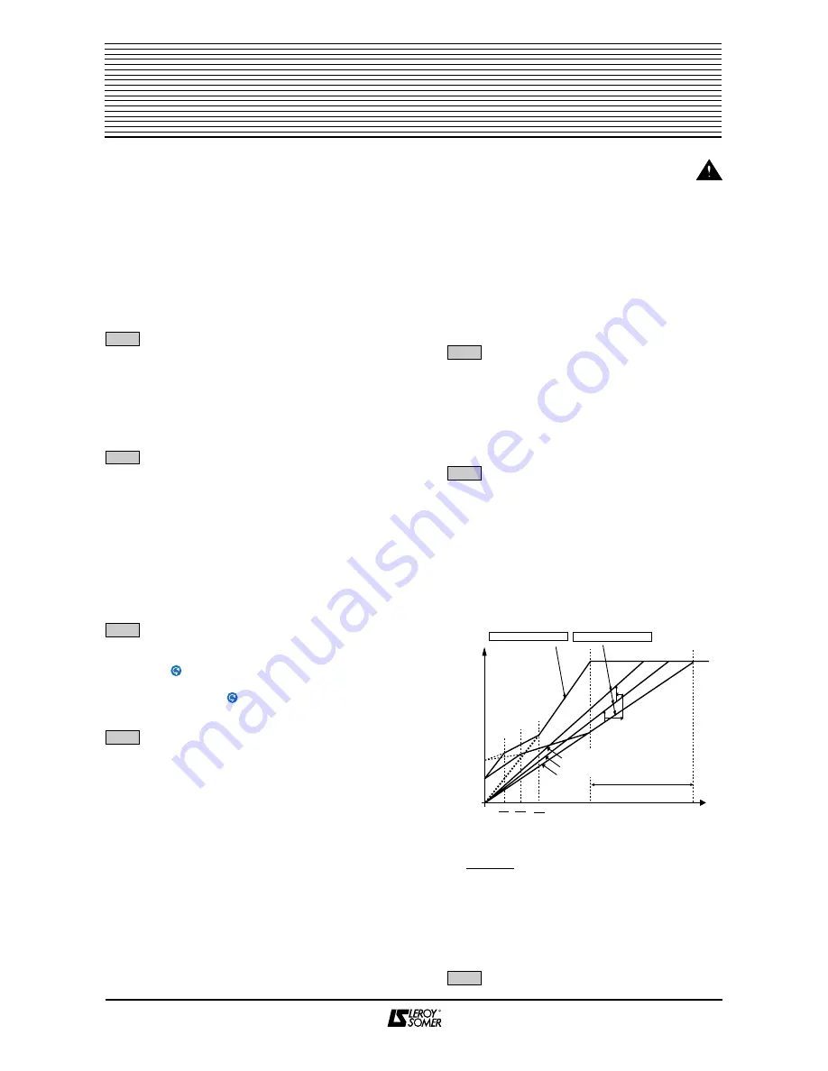
: Selection - fixed or dynamic U/f characteristic
Adjustment range : 0 or 1.
Factory setting
: 0.
Mnemonic :
C1.
b54 = 0 : the U/f ratio is fixed and set via Pc.
b54 = 1 : the voltage applied to the motor is
automatically reduced depending on the motor load. This
enables a saving in energy and a reduction of noise with
low and variable loads (eg. : centrifugal pump).
This automatic modification of the U/f characteristic will
also modify the maximum voltage frequency (MVF) and
the BOOST action (P6).
Pc value applied when b54 = 1 :
Note : If the motor is at no load, the maximum voltage
frequency (MVF), set via Pc, will be reached for
a frequency which is twice as high.
If the load increases, the voltage increases up to the
fixed U/f ratio, MVF = Pc (set).
: Not used
44
Frequency inverters
FMV 2107
FMV 2307
P
P
5
5
1
1
b
b
5
5
0
0
b
b
5
5
1
1
b
b
5
5
2
2
b
b
5
5
3
3
b
b
5
5
4
4
2
% charge
0,7 x P5
x Pc réglé
b
b
5
5
5
5
100 %
U
N
Boost
9.8
(P6)
Fixed U/f, b54 = 0
Dynamic U/f, b54 = 1
Pc
2 x Pc
Pc
16
Pc
8
Pc
2
50 % load
25 % load
No load
The U/f ratio
increases if the
load increases
f
MVF range
load
set


