


S94P01C -e1
54
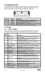
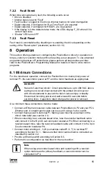
7.2 Diagnostic LEDs
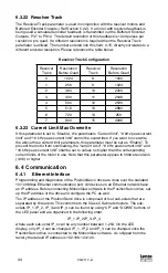
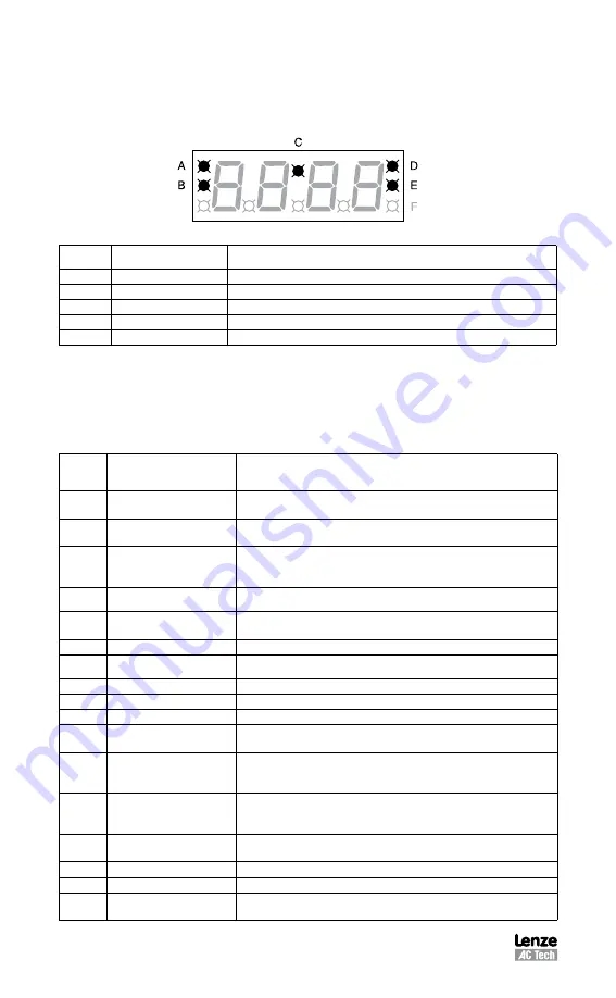
The PositionServo has five diagnostic LEDs mounted on the periphery of the front
panel display as shown in the drawing below. These LEDs are designed to help
monitor system status and activity as well as troubleshoot any faults.
S913
LED
Function
Description
A
Enable
Orange LED indicates that the drive is ENABLED (running).
B
Regen
Yellow LED indicates the drive is in regeneration mode.
C
Data Entry
Yellow LED will flash when changing.
D
Comm Fault
Red LED illuminates upon a communication fault. (in CANbus only)
E
Comm Activity
Green LED flashes to indicate communication activity.
7.3 Faults
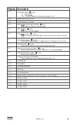
7.3.1 FAULT CODES
Listed herein are fault codes caused mostly by hardware operations. Refer to the
PositionServo Programming Manual for additional faults related to programming.
Fault
Code
Fault
Description
F_OU
Over voltage
Drive bus voltage reached the maximum level, typically due to
motor regeneration
F_FB
Feedback error
Resolver signal lost or at least one motor hall sensor is
inoperable or not connected.
F_OC
Over current
Drive exceeded peak current limit. Software un-capable to
regulate current within 15% for more then 20mS. Usually results
in wrong motor data or poor tuning.
F_Ot
Over temperature
Drive heatsink temperature has been reached maximum rating.
F_EF
External fault input
activated
Digital input was programmed as external fault input and has
been activated.
F_OS
Over speed
Motor reached velocity above its specified limit
F_PE
Excess position error
Position error exceeded maximum value.
F_bd
Bad motor data
Motor profile data invalid or no motor is selected
F_EP
EPM failure
EPM fails on power up.
EP-
EPM missing
EPM not recognized (connected) on power up.
F_09
Motor over temperature
Optional motor temperature sensor (PTC) indicates that the
motor windings have reached maximum temperature
F_ 0
Subprocessor
failure
Error in data exchange between processors. Usually happens
when EMI level is high resulting from poor shielding and
grounding.
F_ 4
Undervoltage
Happens bus voltage level drops below 50% of nominal bus
voltage while drive is operating. Attempt to enable drive with low
bus voltage also result in this fault.
F_ 5
Hardware overload
protection
Happens if phase current at any time becomes higher than 400%
of total drive’s current capability for more then 5uS.
F_32
Positive Limit Switch
Positive limit switch is activated
F_33
Negative Limit Switch
Negative limit switch is activated
F_36
Drive Disabled by
User at Enable Input
Drive disabled while operating or attempt to enable drive without
deactivating “Inhibit input”. “Inhibit” input has reverse polarity.


