


S94P01C -e1
49
6.5.6 Adjust Analog Voltage Offset
This control button is useful to allow the drive to automatically adjust the analog input
voltage offset. To use it, command the external reference source input at AIN1+ and
AIN1- (P3.24 and 25) to zero volts and then click this button. Any offset voltage at the
analog input will be adjusted out and the adjustment value will be stored in the “Analog
input offset” parameter.
6.6 Digital I/O
The PositionServo has four digital outputs. These outputs can be either assigned to
one of the following functions, or be used by the drives internal User Program
• Not Assigned
No special function assigned. Output can be used by the User
Program.
• Zero Speed
Output activated when drive is at zero speed, refer to “Velocity
Limits Group” (Section 6.7) for settings.
• In Speed Window
Output activated when drive is in set speed window, refer to
“Velocity Limits Group” (Section 6.7) for settings.
• Current Limit
Output activated when drive detects current limit.
• Run Time Fault
A fault has occurred. Refer to Section 7.3 for details on faults.
• Ready
Drive is enabled.
• Brake
Command for the holding brake option (E94ZAHBK2) for
control of a motor with a holding brake. This output is active
10ms after the drive is enabled and deactivates 10ms before
the drive is disabled.
• In position
Position mode only. Refer to the PositionServo Programming
Manual for details
6.6.1 Digital Input De-bounce Time
Sets de-bounce time for the digital inputs to compensate for bouncing of the switch or
relay contacts. This is the time during an input transition that the signal must be stable
before it is recognized by the drive.
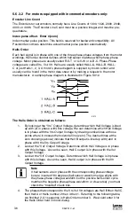
6.6.2 Hard Limit Switch Action
Digital inputs IN_A1 and IN_A2 can be used as limit switches if their function is set
to “Fault” or “Stop and Fault”. Activation of these inputs while the drive is enabled
will cause the drive to Disable and go to a Fault state. The “Stop and Fault” action is
available only in Position mode when the “Reference” parameter is set to “Internal”,
i.e., when the source for the motion is the Trajectory generator. Refer to the
PositionServo Programming Manual for details on “Stop and Fault” behavior.
6.7 Velocity Limits Group
These parameters are active in Velocity Mode Only.
6.7.1 Zero Speed
Specifies the upper threshold for motor zero speed in RPM. When the motor shaft
speed is at or below the specified value the zero speed condition is set to true in the
internal controller logic. The zero speed condition can also trigger a programmable
digital output, if selected.
6.7.2 Speed Window
Specifies the speed window width used with the “In speed window” output.


