


S94P01C -e1
52
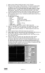
6.10 Tools Group
6.10.1 Oscilloscope Tool
The oscilloscope tool gives real time representation of different signals inside the
PositionServo drive and is helpful when debugging and tuning drives. Operation of
the oscilloscope tool is described in more detail in the MotionView Software User’s
Manual. The following are the signals that can be observed with the oscilloscope tool:
Phase Current (RMS):
Motor phase current
Phase Current (Peak):
Motor peak current
Iq Current:
Measures the motor Iq (torque producing) current
Motor Velocity:
Actual motor speed in RPM
Commanded Velocity:
Desired motor speed in RPM (velocity mode only)
Velocity Error:
Difference in RPM between actual and commanded
motor speed
Position Error:
Difference between actual and commanded position
(Step & Direction mode only)
Bus voltage:
DC bus voltage
Analog input:
Voltage at drive’s analog input
Absolute position:
Absolute position (actual position)
Target position:
Requested position
6.10.2 Run Panels
Check Phasing
This button activates the Autophasing feature as described in section 5.6.2. However,
in this panel only the motor phasing is checked, the motor data is not modified.
6.11 Faults Group
Faults Group loads the fault history from the drive. The 8 most recent faults are
displayed with the newer faults replacing the older faults in a first-in, first-out manner.
In all cases fault # 0 is the most recent fault. To clear the faults history from the
drive’s memory click on the “Reset Fault history” button. Each fault has its code and
explanation of the fault. See section 7.3 for details on faults.
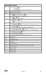
7 Display and Diagnostics
7.1 Diagnostic Display
The PositionServo drives are equipped with a diagnostic LED display and 3 push
buttons to select displayed information and to edit a limited set of parameter values.
Parameters can be scrolled by using the “UP” and “DOWN” (
) buttons. To view a
value, press “Enter”( ). To return back to scroll mode press “Enter” again.
After pressing the ”Enter” button on editable parameters, the yellow LED “C” (see
figure in the next section) will blink indicating that parameter value can be changed.
Use “UP” and “DOWN” buttons to change the value. Press “Enter” to store new setting
and return back to scroll mode.


