


S94P01C -e1
22
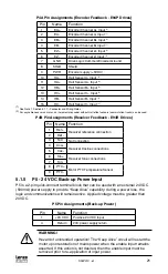
5.1.6 P6 - Braking Resistor and DC Bus
P6 is a 5-pin quick-connect terminal block that can be used with an external braking
resistor (the PositionServo has the regen circuitry built-in). The Brake Resistor
connects between the Positive DC Bus (either P6.1 or 2) and P6.3.
P6 Terminal Assignments (Brake Resistor and DC Bus)
Pin
Terminal
Function
1
B+
Positive DC Bus / Brake Resistor
2
B+
3
BR
Brake Resistor
4
B-
Negative DC Bus
5
B-
5.1.7 Connectors and Wiring Notes
Note 1 - Encoder Inputs
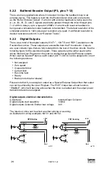
Each of the encoder output pins on P3 is a buffered pass-through of the corresponding
input signal on P4, Refer to section 5.2.2 “Buffered Encoder Outputs”. This can
be either from a motor mounted encoder/resolver, (primary feedback), or from an
auxiliary encoder/resolver when a optional feedback module is used.
Via software, these pins can be re-programmed to be a buffered pass through of the
signals from a feedback option card. This can be either the second encoder option
module (E94ZAENC1) or an encoder emulation of the resolver connected to the
resolver option module (E94ZARSV2 or E94ZARSV3).
Note 2 - Encoder Outputs
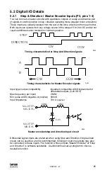
An external pulse train signal (“step”) supplied by an external device, such as a PLC
or stepper indexer, can control the speed and position. of the servomotor. The speed
of the motor is controlled by the frequency of the “step” signal, while the number
of pulses that are supplied to the PositionServo 940 determines the position of the
servomotor. “DIR” input controls direction of the motion.
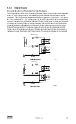
Note 3 - Digital Input
For the drive to function an ENABLE input must be wired to the drive, and should be
connected to IN_A3, (P3.29), which is, by the default the ENABLE input on the drive.
This triggering mechanism can either be a switch or an input from an external PLC
or Motion Controller. The input can be wired either sinking or sourcing (Ref section
5.2.3). The Enable circuit will accept 5-24V control voltage.
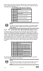
5.1.8 P11 - Resolver Interface Module (option module)
PositionServo drives can operate motors equipped with resolvers from either the (P4)
connection, for a resolver-based (E94R) drive, or from the Resolver option module for
an encoder-based (E94P) drive. The option module connections are made to a 9 pin
D-shell female connector (P11) on the resolver option module E94ZARSV2 (scalable)
or E94ZARSV3 (standard). When the motor profile is loaded from the motor database
or from a custom motor file, the drive will select the primary feedback source based on
the motor data entry.
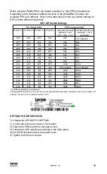
The E94ZARSV3 has a fixed resolution of 1024 PPR prequadrature or 4096
postquadrature. The E94ZARSV2 has a selectable set of 15 resolutions. The
resolution refers to the pulses per revolution (PPR) of the Buffered Encoder Outputs
(P3-7 to P3-12) if the Encoder Repeat Source is set as “Optional Feedback Input” in
MotionView.


