


S94P01C -e1
36
5.6.3.2 For motors equipped with incremental encoders only:
Encoder Line Count
The Encoders for servomotors normally have Line Counts of 1000, 1024, 2000, 2048,
4000, or 4096. The Encoder Line Count must be a positive integer and must be pre-
quadrature.
Index pulse offset. Enter 0 (zero)
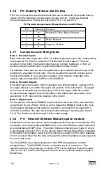
Index marker pulse position. This field is reserved for backward compatibility. All
PositionServo drives determine actual marker pulse position automatically.
Halls Order
Each hall signal is in phase with one of the three phase-phase voltages from the motor
windings. Hall order number defines which hall sensor matches which phase-phase
voltage. Motor phases are usually called R-S-T or U-V-W or A-B-C. Phase-Phase
voltages are called Vrs, Vst, Vtr. Halls are usually called HALL-A, HALL-B, HALL-
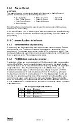
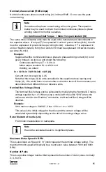
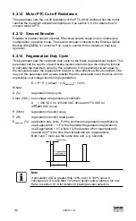
C or just Halls 1, 2, 3. A motor’s phase diagram is supplied by motor vendor and
usually can be found in the motor data sheet or by making a request to the motor
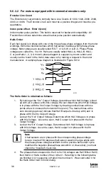
manufacturer. A sample phase diagram is illustrated in Figure S912.
S912
The Halls Order is obtained as follows:
1. By looking at the “Vrs” Output Voltage, determine which Hall Voltage is lined
up with (or in phase with) this voltage. We can determine which Hall Voltage
is in phase with the Vrs Output Voltage by drawing vertical lines at those
points where it crosses the horizontal line (zero). The dashed lines at the
zero crossings (above) indicate that Hall B output is lined up with (and in
phase with) the Vrs Output Voltage.
2. Look at the “Vst” Output Voltage. Determine which Hall Voltage is in phase
with this Voltage. As can be seen, Hall C output is in phase with the Vst
Output Voltage.
3. Look at the “Vtr” Output Voltage. Determine which Hall Voltage is in phase
with this Voltage. As can be seen, Hall A output is in phase with the Vtr
Output Voltage.
Note
If hall sensors are in phase with the corresponding phase voltage
but are inverted 180 degrees (hall sensor waveform edge aligns with
the phase-phase voltage waveform but the positive hall sensor cycle
matches the negative phase-phase waveform or visa-versa), you must
check the “Inverted” check box.
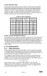
4. The phases that correspond to the Vrs Vst Vtr voltages are Hall B then Hall C
then Hall A or Halls number 2 then 3 then 1. Referring to the following table,
we find that 2-3-1 sequence is Halls Order number 3. We would enter 3 for
the Halls Order field in motor dialog.


