


S94P01C -e1
10
2.4 Digital I/O Ratings
Scan
Times
Linearity
Temperature Drift
Offset
Current
Input
Impedance
Voltage
Range
Units
ms
%
%
%
mA
Ohm
VDC
Digital Inputs
(1)
0.02
(2)
Depend on load
2.2 k
5-24
Digital Outputs
0.052
(2)
100 max
N/A
30 max
Analog Inputs
0.052
± 0.013
0.1% per °C rise
± 0 adjustable
Depend on load
47 k
± 18
Analog Outputs
0.052
0.1% per °C rise
± 0 adjustable
10 max
N/A
± 10
(1) Inputs do not have scan time. Their values are read directly by indexer program statement.
De-bounce time is programmable and can be set as low as 0. Propagation delay is typical 20 us
(2) Time when output has an assigned function.
2.5 Environment
Vibration
2 g (10 - 2000 Hz)
Ambient Operating Temperature Range
0 to 40ºC
Ambient Storage Temperature Range
-10 to 70ºC
Temperature Drift
0.1% per ºC rise
Humidity
5 - 90% non-condensing
Altitude
1500 m/5000 ft [derate by 1% per 300m
(1000 ft) above 1500m (5000 ft)]
2.6 Operating Modes
Torque
Reference
± 10 VDC 16-bit; scalable
Torque Range
100:1
Current-Loop Bandwidth
Up to 3 kHz
Velocity
Reference
± 10 VDC or 0…10 VDC; scalable
Regulation
± 1 RPM
Velocity-Loop Bandwidth
Up to 400 Hz
Speed Range
5000:1 with 5000 ppr encoder
Position
Reference
0…2 MHz Step and Direction or
2 channels quadrature input; scalable
Minimum Pulse Width
500 nanoseconds
Loop Bandwidth
Up to 200 Hz
Accuracy
±1 encoder count for encoder feedabck
±1.32 arc-minutes for resolver feedback (14-bit resolution)
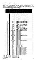
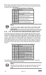
2.7 Connections and I/O
Mains Power
4-pin removable terminal block
(P1)
Ethernet Port
Standard RJ45 Connector
(P2)
I/O Connector
Standard 50-pin SCSI.
(P3)
- Buffered Encoder Output
In 50-pin SCSI controller connector
(P3)
- Digital Inputs
11 programmable, 1 dedicated (5-24V)
(P3)
- Digital Outputs
4 programmable, 1 dedicated(5-24V @ 100mA)
(P3)
- Analog Input
2 differential; ±10 VDC (one16 bit, one 10 bit)
(P3)
- Analog Output
1 single ended; ±10 VDC (10-bit)
(P3)
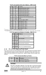
Encoder Feedback (E94P drive)
Feedback connector is a 15-pin D-shell
(P4)
Resolver Feedback (E94R drive)
Feedback connector is a 9-pin D-shell
(P4)
24VDC Power “Keep Alive”
2-pin removable terminal block
(P5)
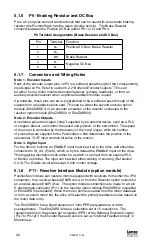
Regen and Bus Power
5-pin removable terminal block
(P6)
Motor Power
6-pin pin removable terminal block
(P7)
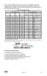
Comm Option Bay
Optional Comm Modules (CAN, RS485)
(P21)
Resolver feedback (option bay)
Option module with standard 9-pin D-shell
(P11)
Encoder Feedback (option bay)
Option module with standard 9-pin D-shell
(P12)
Windows® Software:
MotionView (Windows 98, NT, 2000, XP)


