


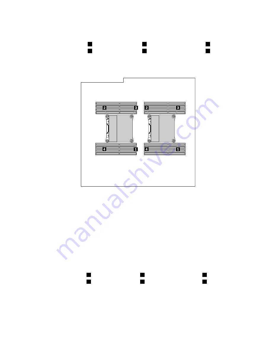
7. Follow this sequence to remove the four screws that secure the heat sink and fan assembly to the
system board:
a. Partially remove screw
1
, then fully remove screw
2
, and then fully remove screw
1
.
b. Partially remove screw
3
, then fully remove screw
4
, and then fully remove screw
3
.
Note:
Carefully remove the four screws from the system board to avoid any possible damage to the
system board. The four screws cannot be removed from the heat sink and fan assembly.
Figure 83. Removing the heat sink and fan assembly
8. Lift the failing heat sink and fan assembly off the system board.
Notes:
• You might have to gently twist the heat sink and fan assembly to free it from the microprocessor.
• Do not touch the thermal grease while handling the heat sink and fan assembly.
9. To install the new heat sink and fan assembly, position the new heat sink and fan assembly on the
system board so that the four screws are aligned with the holes on the system board.
Note:
Position the new heat sink and fan assembly so that the heat sink and fan assembly cable is
toward the heat-sink-and-fan-assembly connector on the system board.
10. Follow the following sequence to install the four screws to secure the new heat sink and fan assembly.
Do not over-tighten the screws.
a. Partially tighten screw
1
, then fully tighten screw
2
, and then fully tighten screw
1
.
b. Partially tighten screw
3
, then fully tighten screw
4
, and then fully tighten screw
3
.
11. Connect the cable of the new heat sink and fan assembly to the system board. See “Locating parts on
the system board” on page 34.
12. Reinstall the direct cooling air baffle. See “Removing and reinstalling the direct cooling air baffle” on
page 128.
What to do next:
• To work with another piece of hardware, go to the appropriate section.
166
ThinkStation P900 Hardware Maintenance Manual
Summary of Contents for ThinkStation P900
Page 1: ...ThinkStation P900 Hardware Maintenance Manual Machine Types 30A4 and 30A5 ...
Page 6: ...iv ThinkStation P900 Hardware Maintenance Manual ...
Page 8: ...vi ThinkStation P900 Hardware Maintenance Manual ...
Page 16: ...8 ThinkStation P900 Hardware Maintenance Manual ...
Page 20: ...12 ThinkStation P900 Hardware Maintenance Manual ...
Page 21: ...1 2 Chapter 1 Read this first Important safety information 13 ...
Page 22: ...1 2 14 ThinkStation P900 Hardware Maintenance Manual ...
Page 27: ...1 2 Chapter 1 Read this first Important safety information 19 ...
Page 28: ...1 2 20 ThinkStation P900 Hardware Maintenance Manual ...
Page 31: ...Chapter 1 Read this first Important safety information 23 ...
Page 68: ...Figure 8 Locking the computer cover 60 ThinkStation P900 Hardware Maintenance Manual ...
Page 72: ...64 ThinkStation P900 Hardware Maintenance Manual ...
Page 86: ...78 ThinkStation P900 Hardware Maintenance Manual ...
Page 104: ...96 ThinkStation P900 Hardware Maintenance Manual ...
Page 118: ...110 ThinkStation P900 Hardware Maintenance Manual ...
Page 202: ...194 ThinkStation P900 Hardware Maintenance Manual ...
Page 206: ...198 ThinkStation P900 Hardware Maintenance Manual ...
Page 210: ...202 ThinkStation P900 Hardware Maintenance Manual ...
Page 217: ......
Page 218: ......