


4. Locate the optical drive bay into which you want to install an optical drive. See “Locating internal
drives” on page 35.
5. Press the clip underneath the plastic cover of the optical drive bay so that the cover is ejected out of the
bay. Then, remove the metal shield in the bay.
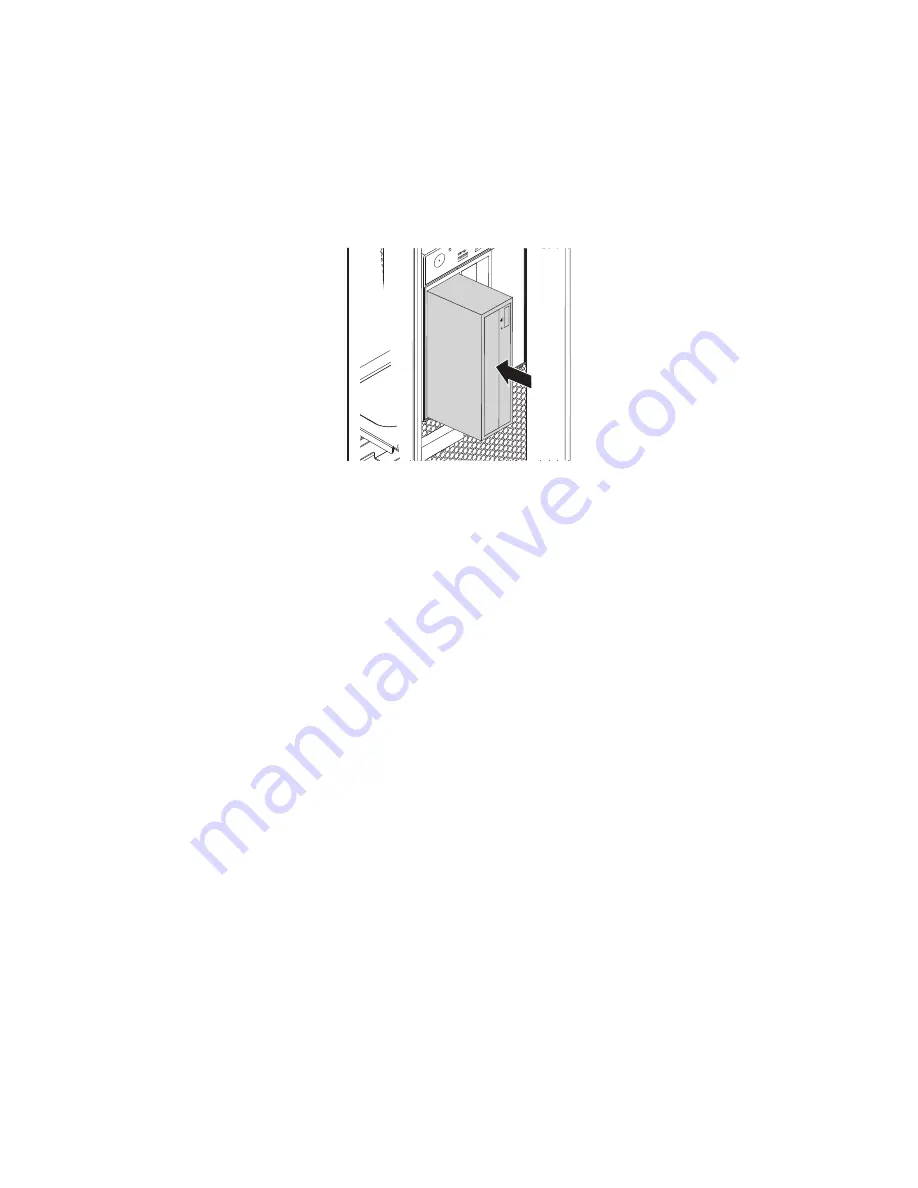
1. Note the orientation of the new optical drive. Then, slide the optical drive into the optical drive bay from
the front of the chassis until it snaps into position.
Figure 35. Installing the optical drive
2. Connect the cables to the optical drive.
Note:
If you install a flex module or a front-access storage enclosure, you might need to connect the
cables to the device, a PCI card, or the system board. See “Locating parts on the system board”
on page 34.
3. Reinstall the direct cooling air baffle. See “Removing and reinstalling the direct cooling air baffle” on
page 128.
What to do next:
• To work with another piece of hardware, go to the appropriate section.
• To complete the installation or replacement, go to “Completing the parts replacement” on page 183.
Installing or replacing a device in the flex module
Important:
Before you replace any FRU, be sure to read and understand Chapter 1 “Read this first:
Important safety information” on page 1.
This section provides instructions on how to install or replace a device in the flex module. Installing and
replacing a device in the flex module involves the following operations:
•
“Installing or replacing a slim optical drive in the flex module” on page 132
•
“Installing or replacing a 29-in-1 card reader in the flex module” on page 135
•
“Installing or replacing an eSATA connector or IEEE 1394 connector in the flex module” on page 137
Installing or replacing a slim optical drive in the flex module
To install or replace a slim optical drive in the flex module, do the following:
1. Remove the flex module out of the front of the computer. See “Removing and installing a device in an
optical drive bay” on page 130.
132
ThinkStation P900 Hardware Maintenance Manual
Summary of Contents for ThinkStation P900
Page 1: ...ThinkStation P900 Hardware Maintenance Manual Machine Types 30A4 and 30A5 ...
Page 6: ...iv ThinkStation P900 Hardware Maintenance Manual ...
Page 8: ...vi ThinkStation P900 Hardware Maintenance Manual ...
Page 16: ...8 ThinkStation P900 Hardware Maintenance Manual ...
Page 20: ...12 ThinkStation P900 Hardware Maintenance Manual ...
Page 21: ...1 2 Chapter 1 Read this first Important safety information 13 ...
Page 22: ...1 2 14 ThinkStation P900 Hardware Maintenance Manual ...
Page 27: ...1 2 Chapter 1 Read this first Important safety information 19 ...
Page 28: ...1 2 20 ThinkStation P900 Hardware Maintenance Manual ...
Page 31: ...Chapter 1 Read this first Important safety information 23 ...
Page 68: ...Figure 8 Locking the computer cover 60 ThinkStation P900 Hardware Maintenance Manual ...
Page 72: ...64 ThinkStation P900 Hardware Maintenance Manual ...
Page 86: ...78 ThinkStation P900 Hardware Maintenance Manual ...
Page 104: ...96 ThinkStation P900 Hardware Maintenance Manual ...
Page 118: ...110 ThinkStation P900 Hardware Maintenance Manual ...
Page 202: ...194 ThinkStation P900 Hardware Maintenance Manual ...
Page 206: ...198 ThinkStation P900 Hardware Maintenance Manual ...
Page 210: ...202 ThinkStation P900 Hardware Maintenance Manual ...
Page 217: ......
Page 218: ......