


Removing and reinstalling the front bezel
Attention
Do not open your computer or attempt any repair before reading and
understanding the “Important safety information” in the
ThinkStation Safety
and Warranty Guide
that came with your computer. To obtain a copy of the
ThinkStation Safety and Warranty Guide
, go to:
http://www.lenovo.com/support
This section provides instructions on how to remove and reinstall the front bezel.
To remove and reinstall the front bezel, do the following:
1.
Remove all media from the drives and turn off all attached devices and the
computer. Then, disconnect all power cords from electrical outlets and
disconnect all cables that are connected to the computer.
2.
Remove the computer cover. See “Removing the computer cover” on page 87.
3.
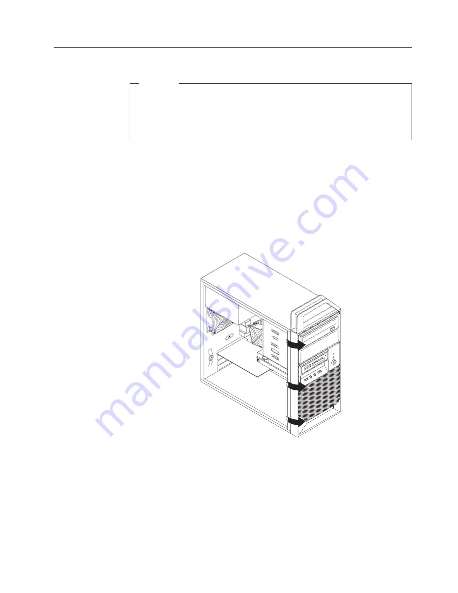
Remove the front bezel by releasing the three plastic tabs on the left side and
pivoting the front bezel outward.
4.
To reinstall the front bezel, align the three plastic tabs on the right side of the
front bezel with the corresponding holes in the chassis, then pivot the front
bezel inwards until it snaps into position on the left side.
5.
To complete the installation, go to “Completing the FRU replacement” on page
122.
Figure 7. Removing the front bezel
Chapter 9. Replacing FRUs
89
Summary of Contents for ThinkStation 4215
Page 1: ......
Page 2: ......
Page 3: ...ThinkStation Hardware Maintenance Manual ...
Page 17: ...Chapter 2 Safety information 11 ...
Page 18: ...12 Hardware Maintenance Manual ...
Page 19: ... 18 kg 37 lbs 32 kg 70 5 lbs 55 kg 121 2 lbs 1 2 Chapter 2 Safety information 13 ...
Page 23: ...Chapter 2 Safety information 17 ...
Page 24: ...1 2 18 Hardware Maintenance Manual ...
Page 25: ...Chapter 2 Safety information 19 ...
Page 26: ...1 2 20 Hardware Maintenance Manual ...
Page 33: ...Chapter 2 Safety information 27 ...
Page 34: ...28 Hardware Maintenance Manual ...
Page 35: ...1 2 Chapter 2 Safety information 29 ...
Page 39: ...Chapter 2 Safety information 33 ...
Page 40: ...1 2 34 Hardware Maintenance Manual ...
Page 44: ...38 Hardware Maintenance Manual ...
Page 54: ...48 Hardware Maintenance Manual ...
Page 130: ...124 Hardware Maintenance Manual ...
Page 179: ......
Page 180: ...Part Number 71Y8031 Printed in USA 1P P N 71Y8031 ...