


6.
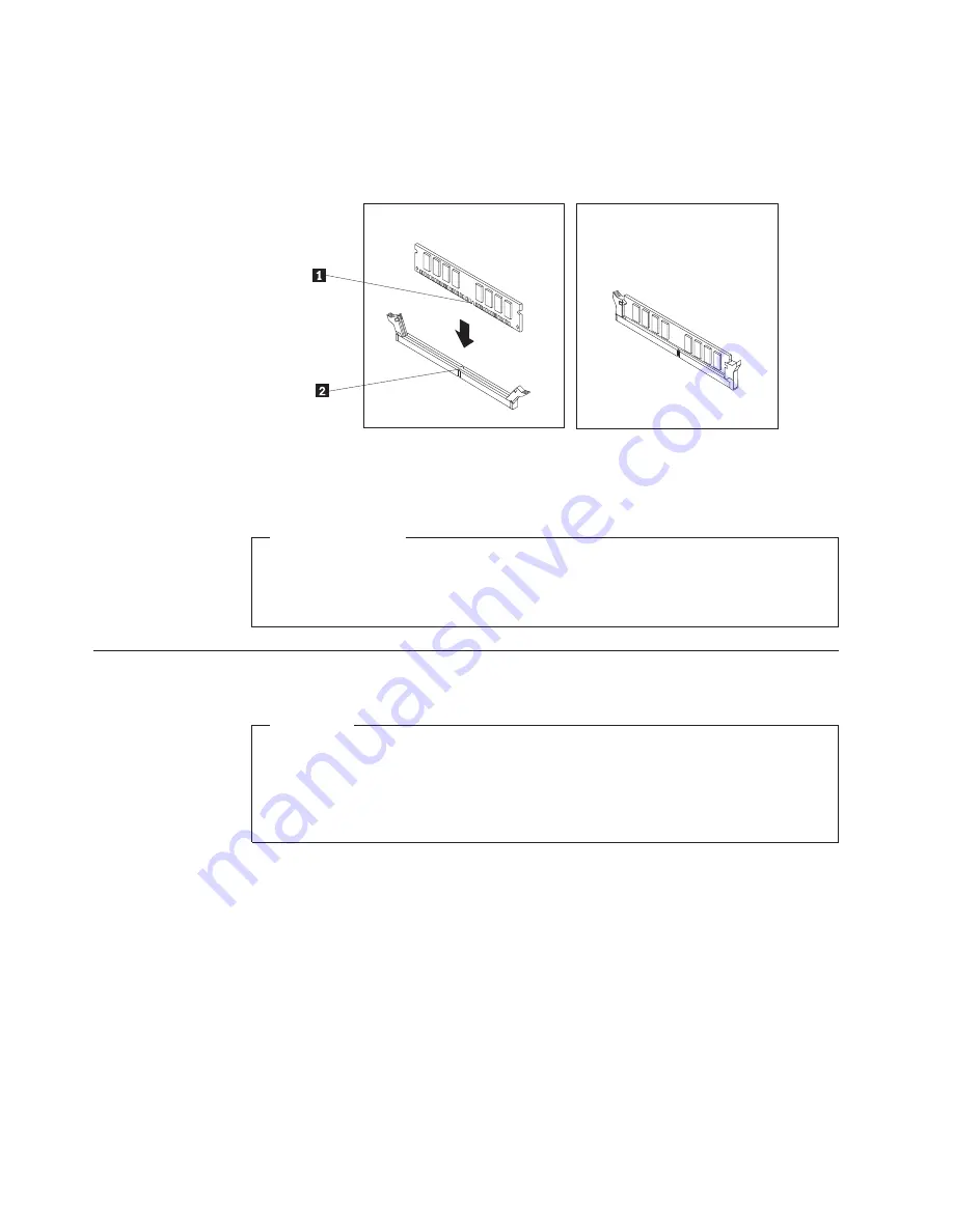
Position the new memory module over the memory slot. Make sure that the
notch
1
on the memory module aligns correctly with the slot key
2
on the
system board. Push the memory module straight down into the slot until the
retaining clips close.
7.
Reinstall the PCI Express x16 graphics card if you have removed it.
What to do next:
v
To work with another piece of hardware, go to the appropriate section.
v
To complete the installation or replacement, go to “Completing the FRU
replacement” on page 122.
Installing or replacing the optical drive
Attention
Do not open your computer or attempt any repair before reading and
understanding the “Important safety information” in the
ThinkStation Safety
and Warranty Guide
that came with your computer. To obtain a copy of the
ThinkStation Safety and Warranty Guide
, go to:
http://www.lenovo.com/support
This section provides instructions on how to install or replace the optical drive.
To install or replace an optical drive, do the following:
1.
Remove all media from the drives and turn off all attached devices and the
computer. Then, disconnect all power cords from electrical outlets and
disconnect all cables that are connected to the computer.
2.
Remove the computer cover. See “Removing the computer cover” on page 87.
3.
Remove the front bezel. See “Removing and reinstalling the front bezel” on
page 89.
4.
Depending on whether you are installing or replacing an optical drive, do one
of the following:
v
If you are installing a secondary optical drive, remove the plastic panel in the
front bezel for the drive bay you want to use. If there is a metal static shield
installed in the drive bay, remove the metal static shield.
Figure 13. Installing a memory module
94
Hardware Maintenance Manual
Summary of Contents for ThinkStation 4215
Page 1: ......
Page 2: ......
Page 3: ...ThinkStation Hardware Maintenance Manual ...
Page 17: ...Chapter 2 Safety information 11 ...
Page 18: ...12 Hardware Maintenance Manual ...
Page 19: ... 18 kg 37 lbs 32 kg 70 5 lbs 55 kg 121 2 lbs 1 2 Chapter 2 Safety information 13 ...
Page 23: ...Chapter 2 Safety information 17 ...
Page 24: ...1 2 18 Hardware Maintenance Manual ...
Page 25: ...Chapter 2 Safety information 19 ...
Page 26: ...1 2 20 Hardware Maintenance Manual ...
Page 33: ...Chapter 2 Safety information 27 ...
Page 34: ...28 Hardware Maintenance Manual ...
Page 35: ...1 2 Chapter 2 Safety information 29 ...
Page 39: ...Chapter 2 Safety information 33 ...
Page 40: ...1 2 34 Hardware Maintenance Manual ...
Page 44: ...38 Hardware Maintenance Manual ...
Page 54: ...48 Hardware Maintenance Manual ...
Page 130: ...124 Hardware Maintenance Manual ...
Page 179: ......
Page 180: ...Part Number 71Y8031 Printed in USA 1P P N 71Y8031 ...