


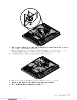


11. Position the new inverter on the main bracket and align the two screw holes in the new inverter with
those in the main bracket.
12. Connect the three cables to the new inverter.
13. Install the two screws
1
that secure the new inverter to the main bracket.
14. Reinstall the right I/O assemblies. See “Replacing the right I/O assemblies” on page 77.
15. Reinstall the optical drive. See “Replacing the optical drive” on page 76.
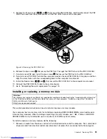
16. Reinstall the hard disk drive. See “Replacing the hard disk drive” on page 74.
17. Go to “Removing the computer cover” on page 73.
Replacing the power supply
Attention
Do not open your computer or attempt any repair before reading and understanding the “Important safety
information” in the
ThinkCentre Safety and Warranty Guide
that came with your computer. To obtain a copy
of the
ThinkCentre Safety and Warranty Guide
, go to:
http://www.lenovo.com/support
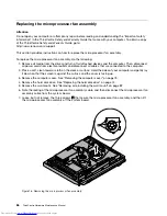
This section provides instructions on how to replace the power supply.
To replace the power supply, do the following:
1. Remove all media from the drives and turn off all attached devices and the computer. Then, disconnect
all power cords from electrical outlets and disconnect all cables that are connected to the computer.
2. Place a soft, clean towel or cloth on the desk or surface. Hold the sides of your computer and gently lay
it down so that the screen is against the surface and the cover is facing up.
3. Remove the computer cover. See “Removing the computer cover” on page 73.
4. Remove the hard disk drive. See “Replacing the hard disk drive” on page 74.
5. Remove the optical drive. See “Replacing the optical drive” on page 76.
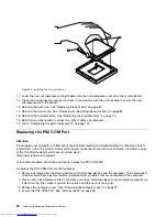
6. Remove the PS2 COM Port. See “Replacing the PS2 COM Port” on page 92.
7. Locate the power supply. See “FRU locations” on page 69.
8. Disconnect the power supply cables from the system board. See “System board parts and connectors”
on page 71.
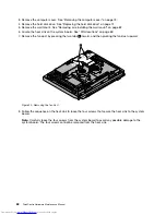
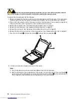
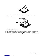
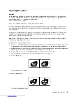
9. Remove the four screws
1
that secure the power supply. Then remove the two screws
3
that secure
the power cord connector bracket. Note the routing of the power cord connector cable
2
. Lift the
power supply up to remove it from the computer main bracket.
Chapter 8
.
Replacing FRUs
81
Summary of Contents for ThinkCentre 7570
Page 2: ......
Page 15: ...Chapter 2 Safety information 9 ...
Page 19: ...Chapter 2 Safety information 13 ...
Page 20: ...1 2 14 ThinkCentre Hardware Maintenance Manual ...
Page 21: ...Chapter 2 Safety information 15 ...
Page 27: ...Chapter 2 Safety information 21 ...
Page 31: ...Chapter 2 Safety information 25 ...
Page 38: ...32 ThinkCentre Hardware Maintenance Manual ...
Page 202: ...196 ThinkCentre Hardware Maintenance Manual ...
Page 207: ......
Page 208: ...Part Number 0A22568 Printed in USA 1P P N 0A22568 0A22568 ...


