


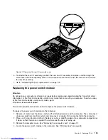


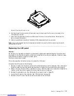


6. Note the locations of all cable connections that prevent you from lifting the computer main bracket, and
disconnect all cables. See “System board parts and connectors” on page 71.
7. Lift the computer main bracket off the front bezel.
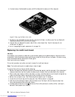
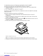
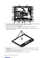
8. Gently rip the three pieces of black tape
1
, and then lift the LCD bezel out of the computer.
Note:
Do not break the tape or remove the tape from the computer. You will need the tape when
installing the new LCD panel.
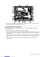
9. Place the new LCD panel into the front bezel, and then stick the three pieces of black tape back to
the LCD panel.
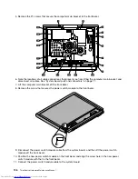
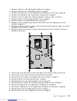
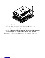
10. Position the computer main bracket over the LCD panel. Make sure the screw holes in the computer
main bracket align with those in the front bezel.
11. Reinstall all the 21 screws that secure the main bracket to the front bezel.
112
ThinkCentre Hardware Maintenance Manual
Summary of Contents for ThinkCentre 7570
Page 2: ......
Page 15: ...Chapter 2 Safety information 9 ...
Page 19: ...Chapter 2 Safety information 13 ...
Page 20: ...1 2 14 ThinkCentre Hardware Maintenance Manual ...
Page 21: ...Chapter 2 Safety information 15 ...
Page 27: ...Chapter 2 Safety information 21 ...
Page 31: ...Chapter 2 Safety information 25 ...
Page 38: ...32 ThinkCentre Hardware Maintenance Manual ...
Page 202: ...196 ThinkCentre Hardware Maintenance Manual ...
Page 207: ......
Page 208: ...Part Number 0A22568 Printed in USA 1P P N 0A22568 0A22568 ...