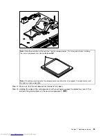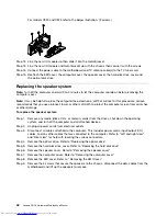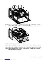
Step 14. Holding the sides of the microprocessor with your ngers, position the microprocessor so that the
notches on the microprocessor are aligned with the tabs in the microprocessor socket.
Important:
To avoid damaging the microprocessor contacts, keep the microprocessor completely level
while installing it into the socket.
Step 15. Lower the microprocessor straight down into its socket on the motherboard.
Step 16. To secure the microprocessor in the socket, close the microprocessor retainer and lock it into
position with the small handle.
Step 17. Use a thermal grease syringe to place 5 drops of grease on the top of the microprocessor. Each
drop of grease should be 0.03ml (3 tick marks on the grease syringe).
Step 18. Reattach the heatsinl, the EMI cover, the computer cover, the speaker cover, the hard disk drive
cover and the optical disk drive.
Replacing the rear I/O module
Note:
Turn off the computer and wait 3 to 5 minutes to let the computer cool down before removing the
computer cover.
46
Lenovo C2/C3 Hardware Maintenance Manual
Summary of Contents for C220
Page 2: ...Lenovo C2 C3 Hardware Maintenance Manual ...
Page 3: ......
Page 5: ...ii Lenovo C2 C3 Hardware Maintenance Manual ...
Page 7: ...2 Lenovo C2 C3 Hardware Maintenance Manual ...
Page 15: ...10 Lenovo C2 C3 Hardware Maintenance Manual ...
Page 25: ...20 Lenovo C2 C3 Hardware Maintenance Manual ...


