background image

Page 37

Unit Start−Up

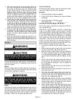
FOR YOUR SAFETY READ BEFORE LIGHTING

WARNING

Do not use this furnace if any part has been underwa-
ter. Immediately call a licensed professional service
technician (or equivalent) to inspect the furnace and
to replace any part of the control system and any gas
control which has been under water.

WARNING

If overheating occurs or if gas supply fails to shut off,
shut off the manual gas valve to the appliance before
shutting off electrical supply.

CAUTION

Before attempting to perform any service or mainte-
nance, turn the electrical power to unit OFF at dis-
connect switch.

WARNING

During blower operation, the ECM motor emits ener-
gy that may interfere with pacemaker operation. In-
terference is reduced by both the sheet metal cabinet
and distance.

BEFORE LIGHTING

 smell all around the appliance area

for gas. Be sure to smell next to the floor because some gas
is heavier than air and will settle on the floor.

The gas valve on the G60UHV(X) unit may be equipped
with either a gas control knob or gas control switch. Use
only your hand to move the control switch or to turn the gas
control knob. Never use tools. If the knob will not turn or if
the control switch will not move by hand, do not try to repair
it. Call a licensed professional service technician (or equiv-
alent). Force or attempted repair may result in a fire or ex-
plosion.

Placing the furnace into operation:

G60UHV(X) units are equipped with an automatic ignition
system. Do not attempt to manually light burners on these
furnaces. Each time the thermostat calls for heat, the burn-
ers will automatically light. The ignitor does not get hot
when there is no call for heat on units with an automatic
ignition system.

WARNING

If you do not follow these instructions exactly, a fire
or explosion may result causing property damage,
personal injury or death.

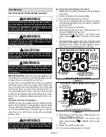
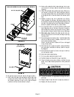
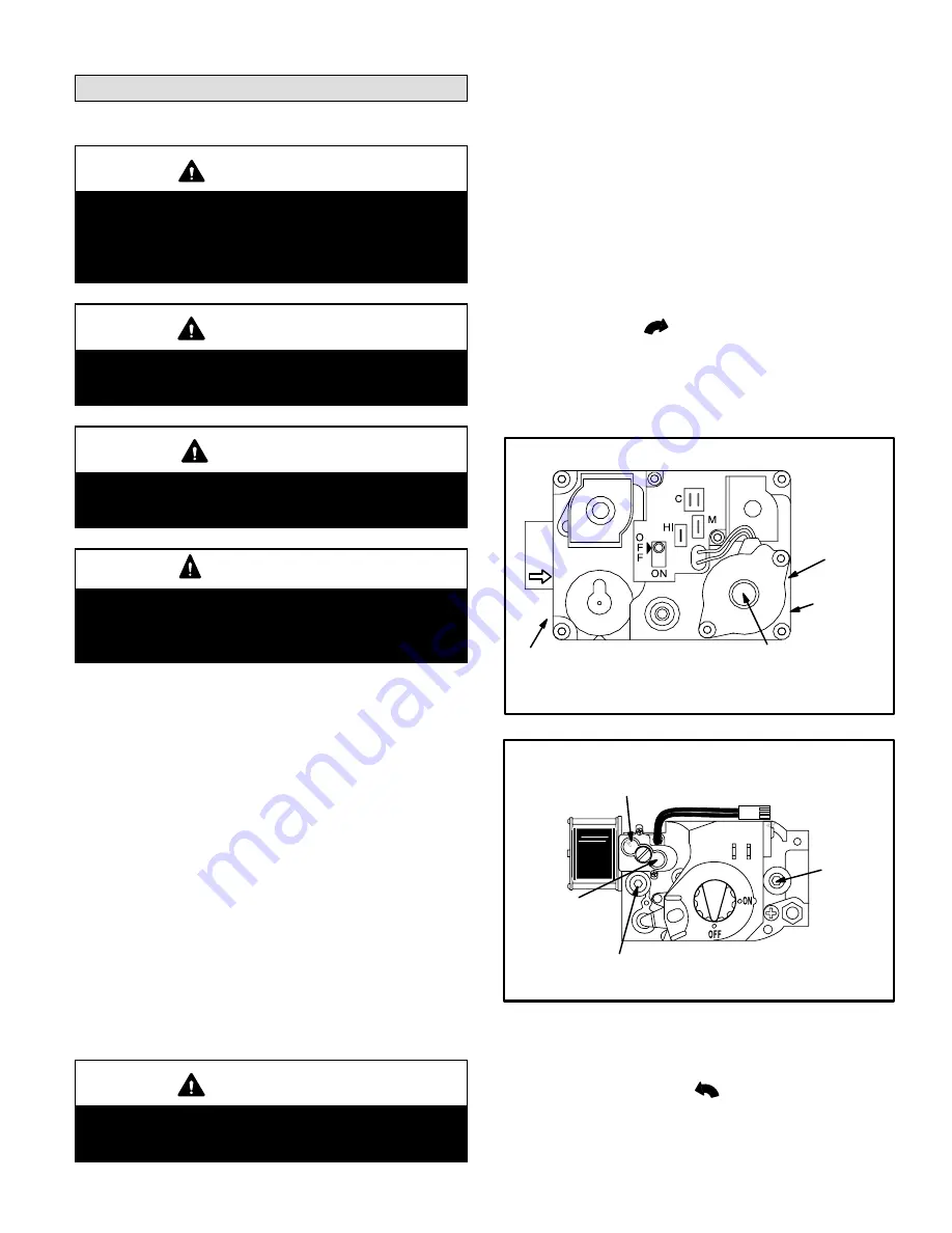
Gas Valve Operation (Figures 26 and 27)

 1 −

STOP

! Read the safety information at the beginning of

this section.

 2 − Set the thermostat to the lowest setting.

 3 − Turn off all electrical power to the unit.
 4 − This furnace is equipped with an ignition device which

automatically lights the burners. Do 

not

 try to light the

burners by hand.

 5 − Remove the upper access panel.
 6 −

White Rodgers 36E Gas Valve − 

Move gas valve con-

trol switch to 

OFF

. See figure 26.

Honeywell VR8205 Gas Valve − 

Turn knob on gas

valve clockwise 

 to 

OFF

. Do not force. See figure

27.

 7 − Wait five minutes to clear out any gas. If you then smell

gas, STOP! Immediately call your gas supplier from a
neighbor’s phone. Follow the gas supplier’s instruc-
tions. If you do not smell gas go to next step.

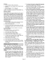
WHITE RODGERS 36E SERIES GAS VALVE

GAS VALVE SHOWN IN OFF POSITION

HIGH FIRE

MANIFOLD

PRESSURE

ADJUSTMENT

ON SIDE 

(under cap)

MANIFOLD

PRESSURE

TAP ON SIDE

INLET PRESSURE

TAP ON SIDE

LOW FIRE MANIFOLD

PRESSURE ADJUSTMENT

ON SIDE (under cap)

FIGURE 26

HONEYWELL VR8205 SERIES GAS VALVE

GAS VALVE SHOWN IN OFF POSITION

MANIFOLD

PRESSURE

TAP

HIGH FIRE

ADJUSTING SCREW 

(under cap)

INLET PRESSURE

TAP

LOW FIRE

ADJUSTING SCREW 

(under cap)

FIGURE 27

 8 −

White Rodgers 36E Gas Valve − 

Move gas valve con-

trol switch to 

ON

.


See figure 26.

Honeywell VR8205 Gas Valve − 

Turn knob on gas

valve counterclockwise 

 to 

ON

. Do not force. See

figure 27.

 9 − Replace the upper access panel.

10− Turn on all electrical power to to the unit.

Summary of Contents for Signature G60UHV36A-070

Page 1: ...tion 39 Service 40 Planned Service 42 Repair Parts List 42 Integrated Control Diagnostic Codes 43 Troubleshooting 44 Start Up Performance Check List 50 WHAT TO DO IF YOU SMELL GAS Do not store or use...

Page 2: ...ingle side with transition which will accommodate 20 x 25 x 1 in 508 x 635 x 25 mm cleanable air filter Required to maintain proper air velocity 2 Return air from single side with optional RAB Return...

Page 3: ...Ox Insert Primary Limit Door Interlock Switch Two Stage Variable Speed Integrated Control Control Transformer Circuit Breaker Gasket Flue Box Gasket Gas Orifices Ignitor Bracket Burner Box Bottom Limi...

Page 4: ...ew York NY 10036 In Canada installation must conform with current National Standard of Canada CSA B149 installation codes for natu ral gas and propane gas burning appliances and equip ment local plumb...

Page 5: ...erature range between 60 F 16 C and 80 F 27 C must be maintained D Air filters must be installed in the system and must be maintained during construction D Air filters must be replaced upon constructi...

Page 6: ...ents as well as all local codes CAUTION Insufficient combustion air can cause headaches nausea dizziness or asphyxiation It will also cause excess water in the heat exchanger resulting in rust ing and...

Page 7: ...have a minimum free area of 1 square inch 645 mm2 per 1 000 Btu 29 kW per hour of total input rating of all gas fired equipment in the confined space Each opening must be at least 100 square inches 6...

Page 8: ...e square inch 645 mm2 per 4 000 Btu 1 17 kW per hour of the total input rating of all equip ment in the enclosure CHIMNEY OR GAS VENT WATER HEATER OUTLET AIR VENTILATION LOUVERS Each end of attic INLE...

Page 9: ...The bolt and washer must be re moved before the furnace is placed into operation Af ter the bolt and washer have been removed the rigid leg will not touch the blower housing NOTE G60UHV 60D 135 units...

Page 10: ...ition and filter FIGURE 7 Return Air Plenum Transition 20 X 25 X 1 508mm X635mm X 25mm Cleanable Filter Optional Return Air Base Upflow Applications Only For use with B C and D cabinets only FIGURE 8...

Page 11: ...tom of the unit 3 Screw another nut onto the bolt on the inside of the fur nace base A flat washer may be added between the nut and the bottom of the unit 4 Adjust the outside nut to the appropriate h...

Page 12: ...Horizontal Applications Return air can be brought in through the end of a furnace installed in a horizontal application The furnace is equipped with a removable bottom panel to facilitate instal lati...

Page 13: ...everse flow of the flue gas may result in incom plete combustion and the formation of carbon monoxide gas This toxic gas might then be distributed throughout the house by the furnace duct system In up...

Page 14: ...e used Drive one self drilling screw through the front and one through each side of the vent pipe and collar See figure 16 Install the first vent connector elbow at a minimum of six inches 152 mm from...

Page 15: ...embly according to the terms of their respective listings and the vent manufacturer s instructions When inspection reveals that an existing chimney is not safe for the intended purpose it shall be reb...

Page 16: ...approved means except vent connectors of listed type B vent material which shall be assembled according to the manufacturer s instructions Joints between sections of single wall connector piping shall...

Page 17: ...0 226 22 339 15 5 22 65 30 130 39 219 49 330 10 29 59 40 121 51 206 64 315 15 35 53 48 112 61 195 76 301 0 0 97 0 202 0 349 0 540 2 10 75 14 149 18 250 20 377 20 5 21 71 29 143 38 242 47 367 20 10 28...

Page 18: ...36 80 225 115 337 15 5 51 63 75 128 102 216 144 326 10 NR NR 95 116 128 201 182 308 15 NR NR NR NR 158 186 220 290 0 35 96 54 200 78 346 114 537 2 37 74 56 148 78 248 113 375 20 5 50 68 73 140 100 239...

Page 19: ...6 69 220 1 21 50 33 89 47 142 64 220 15 2 22 53 35 96 49 153 66 235 3 24 55 36 102 51 163 68 248 1 21 54 33 99 46 157 62 246 20 2 22 57 34 105 48 167 64 259 3 23 60 35 110 50 176 66 271 1 20 62 31 113...

Page 20: ...hile each appliance is operat ing and the other appliances which are not operating re main connected to the common venting system If the vent ing system has been installed improperly you must correct...

Page 21: ...ff valve and union furnished by the installer external to the unit The union must be of the ground joint type IMPORTANT Compounds used on threaded joints of gas piping must be resistant to the actions...

Page 22: ...suresless than or equal to 1 2 psig 3 48 kPa 14 inches w c IMPORTANT When testing pressure of gas lines gas valve must be disconnected and isolated See figure 20 Gas valves can be damaged if subjected...

Page 23: ...ntrol Any electronic air cleaner rated up to one amp can be connected to this terminal with the neutral leg of the circuit being con nected to the one of the provided neutral terminals See figure 25 f...

Page 24: ...ge heat ON delay OFF 10 min utes ON 15 minutes ON Intact Intact Intact S1 T STAT CONTROL TERM STRIP OUTDOOR UNIT 1 Heat 2 Cool NOTE Use DIP switch 2 to set second stage heat ON delay OFF 10 min utes O...

Page 25: ...oling W914 Dehu midification or Harmony III W951 Heat Pumps Wiring Connections 2 Heat 2 Cool OFF Cut Intact Intact S1 T STAT CONTROL TERM STRIP OUTDOOR UNIT 2 Heat 2 Cool with t stat with humidity con...

Page 26: ...Page 26 G60UHV X Schematic Wiring Diagram FIGURE 23...

Page 27: ...tment 9 and 10 Cooling Mode Blower Ramping Profile 11 and 12 Heating Mode Blower Speed INDOOR BLOWER DIP SWITCHES HEATING DIP SWITCHES DIAGNOSTIC LEDs ON BOARD LINKS 1 T stat Heat Stages single or two...

Page 28: ...affects comfort and is adjustable to satisfy individ ual applications Adjust the blower off delay to achieve a supply air temperature between 90 and 110 F at the exact moment that the blower is de en...

Page 29: ...able connection between ter minals DS and R on the integrated control W914 must be cut when the furnace is installed with either the Harmony IIIt zone control or a thermostat which features humidity c...

Page 30: ...Zone Control Applications Minimum blower speed is 426 cfm 200 L s TABLE 17 G60UHV 36B 090 BLOWER MOTOR PERFORMANCE 0 0 to 0 8 w g 0 through 200 Pa External Static Pressure Range Factory Settings Heati...

Page 31: ...speed is 478 cfm 225 L s TABLE 19 G60UHV 60C 090 BLOWER MOTOR PERFORMANCE 0 0 to 0 8 w g 0 through 200 Pa External Static Pressure Range Factory Settings Heating Speed 2 Cooling Speed 4 Speed Adjust N...

Page 32: ...minimum 500 cfm 235 L s Lennox Harmony IIIt Zone Control Applications Minimum blower speed is 478 cfm 225 L s TABLE 21 G60UHV 60C 110 BLOWER MOTOR PERFORMANCE 0 0 to 0 8 w g 0 through 200 Pa External...

Page 33: ...cond stage COOL speed position minimum 500 cfm 235 L s Lennox Harmony IIIt Zone Control Applications Minimum blower speed is 483 cfm 230 L s TABLE 23 G60UHV 60C 110 BLOWER MOTOR PERFORMANCE 0 0 to 0 8...

Page 34: ...er speed is 495 cfm 235 L s TABLE 25 G60UHV 60D 135 BLOWER MOTOR PERFORMANCE 0 0 to 0 8 w g 0 through 200 Pa External Static Pressure Range Factory Settings Heating Speed 2 Cooling Speed 4 Speed Adjus...

Page 35: ...l Applications Minimum blower speed is 495 cfm 235 L s TABLE 27 OPERATING SEQUENCE G60UHV Thermostat with Humidity Control Feature and Single Speed Outdoor Unit OPERATING MODE SYSTEM DEMAND SYSTEM RES...

Page 36: ...d High 65 60 of HIGH COOL Blower immediately changes speed in response to thermostat demand demand Y2 No demand Acceptable High HIGH COOL Call for 1st stage cooling after call for None Humidity level...

Page 37: ...alls for heat the burn ers will automatically light The ignitor does not get hot when there is no call for heat on units with an automatic ignition system WARNING If you do not follow these instructio...

Page 38: ...to the changeover kit installation instruction for the conversion procedure Other Unit Adjustments Primary and Secondary Limits The primary limit is located on the heating compartment vestibule panel...

Page 39: ...warm up period begins The combustion air in ducer continues to operate at low speed 4 After the 20 second warm up period has ended the gas valve is energized on low fire first stage and igni tion occ...

Page 40: ...sizes Flue And Chimney Check the flue pipe chimney and all connections for tight ness and to make sure there is no blockage Electrical 1 Check all wiring for loose connections 2 Check for the correct...

Page 41: ...er the face of burners Visually in spect inside the burners and crossovers for any block age caused by foreign matter Remove any blockage 16 NOx units only Reattach the NOx inserts to the cor bels at...

Page 42: ...oducts must be analyzed and compared to the unit specifications Problems detected during the inspection may make it nec essary to temporarily shut down the furnace until the items can be repaired or r...

Page 43: ...itch failed closed 2 7 Low pressure switch opened during ignition trial or heating demand LIMIT CODE 3 1 Limit switch open WATCHGUARD CODES 4 1 Watchguard Exceeded maximum number of retries 4 2 Watchg...

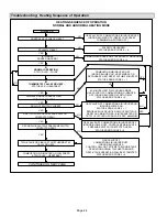
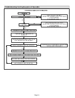
Page 44: ...COMBUSTION AIR INDUCER ON INDOOR BLOWER ON STATUS ERROR CODE 5 1 SEQUENCE HOLDS UNTIL ROLLOUT SWITCH IS RESET AND MAIN POWER IS INTERRUPTED OR T STAT IS CYCLED OFF ON FOR 3 SEC MINIMUM NO YES FIRST L...

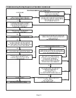
Page 45: ...CONNECTED STATUS ERROR CODE 4 7 YES AT END OF IGNITOR 20 SECOND WARM UP PERIOD 4 SECOND TRIAL FOR IGNITION GAS VALVE OPENS IGNITOR ENERGIZED DURING 4 SECOND TRIAL UNTIL FLAME SENSED YES 4 SECOND FLAME...

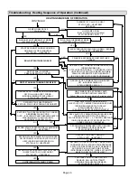
Page 46: ...IRST STAGE HEAT DEMAND SATISFIED GAS VALVE OFF COMBUSTION AIR INDUCER OFF FOLLOWING POST PURGE INDOOR BLOWER OFF WITH DELAY STATUS LED PULSE YES SECOND STAGE HEAT DEMAND SECOND STAGE HEAT DEMAND REQUI...

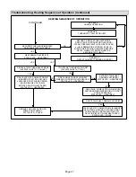
Page 47: ...ODE DIP SWITCH SET AT SINGLE YES YES FIRST AND SECOND STAGE HEAT DEMAND SATISFIED SIMULTANEOUSLY STATUS LED HEARTBEAT YES GAS VALVE OFF COMBUSTION AIR INDUCER OFF AFTER 5 SECOND LOW SPEED POST PURGE P...

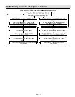
Page 48: ...ZED NO IS THERE PROPER GROUND YES NO INDOOR BLOWER ENERGIZED ON FIRST STAGE COOL SPEED AFTER 2 SECOND DELAY FIRST STAGE DEMAND FOR COOL SATISFIED NO THERMOSTAT CALLS FOR SECOND STAGE COOL COMPRESSOR A...

Page 49: ...TO LOW HEAT SPEED FIRST STAGE HEAT DEMAND SATISFIED YES NO THERMOSTAT CALLS FOR SECOND STAGE HEAT YES INDOOR BLOWER SWITCHES TO HIGH HEAT SPEED AFTER 30 SECOND RECOGNITION PERIOD SECOND STAGE HEAT DE...

Page 50: ...ht Heating Section Thermostat Heat Anticipator Setting Thermostat Level Fuel Type Natural Gas Blower Motor Amps Blower Motor H P Gas Piping Connections Tight Leak Tested Proper Draft State Blower OFF...

Reviews: