


Page 20
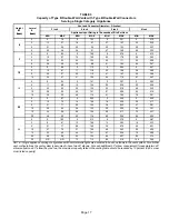
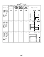
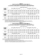
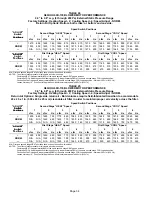
TABLE 7
Vent Connector Capacity
Type B Double−Wall Vents with Single−Wall Metal Connectors
Serving Two or More Category I Appliances
Vent
Connector
Vent and Connector Diameter − D (inches)
Vent
Height
Connector
Rise
3 Inch
4 Inch
5 Inch
6 Inch
Height
H
(feet)
Rise
R
(feet)
Appliance Input Rating in Thousands of Btu Per Hour
(feet)
(feet)
MIN
MAX
MIN
MAX
MIN
MAX
MIN
MAX
1
NR
NR
NR
NR
NR
NR
NR
NR
6
2
NR
NR
NR
NR
NR
NR
168
182
6
3
NR
NR
NR
NR
121
131
174
198
1
NR
NR
79
87
116
138
177
214
15
2
NR
NR
83
94
121
150
185
230
3
NR
NR
87
100
127
160
193
243
1
47
60
77
110
113
175
169
278
30
2
50
62
81
115
117
185
177
290
3
54
64
85
119
122
193
185
300
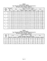
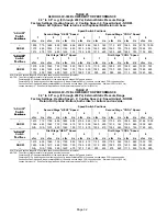
TABLE 8
Common Vent Capacity
Type B Double−Wall Vents with Single−Wall Metal Connectors
Serving Two or More Category I Appliances
Vent
Common Vent Diameter − D (inches)
Vent
Height
4 Inch
5 Inch
6 Inch
7 Inch
Height
H
(feet)
Appliance Input Rating in Thousands of Btu Per Hour
(feet)
FAN + FAN
FAN + NAT
FAN + FAN
FAN + NAT
FAN + FAN
FAN + NAT
FAN + FAN
FAN + NAT
6
89
78
136
113
200
158
304
244
8
98
87
151
126
218
173
331
269
10
106
94
163
137
237
189
357
292
15
121
108
189
159
275
221
416
343
20
131
118
208
177
305
247
463
383
30
145
132
236
202
350
286
533
446
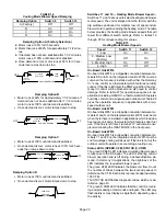
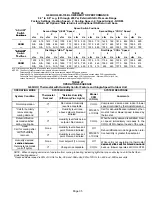
Removal of the Furnace from Common Vent
In the event that an existing furnace is removed from a
venting system commonly run with separate gas ap-
pliances, the venting system is likely to be too large to prop-
erly vent the remaining attached appliances.
Conduct the following test while each appliance is operat-
ing and the other appliances (which are not operating) re-
main connected to the common venting system. If the vent-
ing system has been installed improperly, you
must
correct the system as indicated in the general venting re-
quirements section.
1 − Seal any unused openings in the common venting sys-
tem.
2 − Inspect the venting system for proper size and horizon-
tal pitch. Determine that there is no blockage, restric-
tion, leakage, corrosion, or other deficiencies which
could cause an unsafe condition.
3 − Close all building doors and windows and all doors be-
tween the space in which the appliances remaining
connected to the common venting system are located
and other spaces of the building. Turn on clothes dry-
ers and any appliances not connected to the common
venting system. Turn on any exhaust fans, such as
range hoods and bathroom exhausts, so they will oper-
ate at maximum speed. Do not operate a summer ex-
haust fan. Close fireplace dampers.
4 − Follow the lighting instructions. Turn on the appliance
that is being inspected. Adjust the thermostat so that
the appliance operates continuously.
5 − After the main burner has operated for 5 minutes, test
for leaks of flue gases at the draft hood relief opening.
Use the flame of a match or candle, or smoke from a
cigarette, cigar, or pipe.
6 − After determining that each appliance connected to the
common venting system is venting properly, (step 3)
return all doors, widows, exhaust fans, fireplace damp-
ers, and any other gas−burning appliances to their pre-
vious mode of operation.
7 − If a venting problem is found during any of the preced-
ing tests, the common venting system must be modi-
fied to correct the problem.


