Page 30
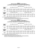
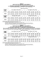
TABLE 16
G60UHV−36A−070 BLOWER MOTOR PERFORMANCE
0.0" to 0.8" w.g. (0 through 200 Pa) External Static Pressure Range
Factory Settings: Heating Speed − 2; Cooling Speed − 4; Speed Adjust − NORM
Speed Switch Positions
ADJUST"
Switch
Second Stage HEAT" Speed
Second Stage COOL" Speed
Switch
Positions
1
2
3
4
1
2
3
4
Positions
cfm
L/s
cfm
L/s
cfm
L/s
cfm
L/s
cfm
L/s
cfm
L/s
cfm
L/s
cfm
L/s
+
895
420
1015
480
1275
600
1320
625
1000
470
1165
550
1260
595
1380
650
NORM
815
385
925
435
1120
530
1170
555
915
430
1035
490
1115
525
1230
580
740
350
845
400
1000
475
1040
490
830
390
945
445
990
470
1085
510
ADJUST"
First Stage HEAT" Speed
First Stage COOL" Speed
ADJUST"
Switch
P
iti
1
2
3
4
1
2
3
4
S
tc
Positions
cfm
L/s
cfm
L/s
cfm
L/s
cfm
L/s
cfm
L/s
cfm
L/s
cfm
L/s
cfm
L/s
+
820
390
930
440
1140
540
1195
565
730
3455
810
385
865
410
910
430
NORM
755
355
855
405
1020
480
1060
500
670
315
745
350
785
370
850
400
695
325
775
365
920
435
965
455
630
295
690
325
725
340
770
365
NOTES − The effect of static pressure is included in air volumes shown.
First stage HEAT is approximately
91%
of the same second stage HEAT speed position.
First stage COOL (two−stage air conditioning units only) is approximately
70%
of the same second stage COOL speed position.
Continuous Fan Only speed is approximately
38%
of the same second stage COOL speed position − minimum 500 cfm (235 L/s).
Lennox Harmony III
t
Zone Control Applications − Minimum blower speed is 426 cfm (200 L/s).
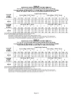
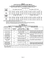
TABLE 17
G60UHV−36B−090 BLOWER MOTOR PERFORMANCE
0.0" to 0.8" w.g. (0 through 200 Pa) External Static Pressure Range
Factory Settings: Heating Speed − 2; Cooling Speed − 4; Speed Adjust − NORM
Speed Switch Positions
ADJUST"
Switch
Second Stage HEAT" Speed
Second Stage COOL" Speed
Switch
Positions
1
2
3
4
1
2
3
4
Positions
cfm
L/s
cfm
L/s
cfm
L/s
cfm
L/s
cfm
L/s
cfm
L/s
cfm
L/s
cfm
L/s
+
N/A
N/A
1025
485
1265
600
1320
625
1005
475
1165
550
1260
595
1385
655
NORM
N/A
N/A
N/A
N/A
1125
530
1170
555
905
425
1035
490
1110
525
1225
580
N/A
N/A
N/A
N/A
1010
475
1045
495
825
390
940
445
1000
470
1090
515
ADJUST"
First Stage HEAT" Speed
First Stage COOL" Speed
ADJUST"
Switch
P
iti
1
2
3
4
1
2
3
4
S
tc
Positions
cfm
L/s
cfm
L/s
cfm
L/s
cfm
L/s
cfm
L/s
cfm
L/s
cfm
L/s
cfm
L/s
+
N/A
N/A
940
445
1140
540
1185
560
725
340
810
385
860
405
920
435
NORM
N/A
N/A
N/A
N/A
1030
485
1065
505
670
315
740
350
785
370
840
395
N/A
N/A
N/A
N/A
925
435
950
450
625
295
695
330
725
345
770
365
N/A − First and second stage HEAT positions shown cannot be used on this model.
NOTES − The effect of static pressure is included in air volumes shown.
First stage HEAT is approximately
91%
of the same second stage HEAT speed position.
First stage COOL (two−stage air conditioning units only) is approximately
70%
of the same second stage COOL speed position.
Continuous Fan Only speed is approximately
38%
of the same second stage COOL speed position − minimum 500 cfm (235 L/s).
Lennox Harmony III
t
Zone Control Applications − Minimum blower speed is 453 cfm (215 L/s).

