background image

Page 25

Compounds used on gas piping threaded joints should be
resistant to action of liquefied petroleum gases.

C−Testing Gas Piping

CAUTION

If a flexible gas connector is required or allowed by
the authority that has jurisdiction, black iron pipe
shall be installed at the gas valve and extend outside
the furnace cabinet.

IMPORTANT

In case emergency shutdown is required, turn off
the main shut-off valve and disconnect the main
power to unit.  These controls should be properly
labeled by the installer.

WARNING

Do not exceed 600 in−lbs (50 ft−lbs) torque when
attaching the gas piping to the gas valve.

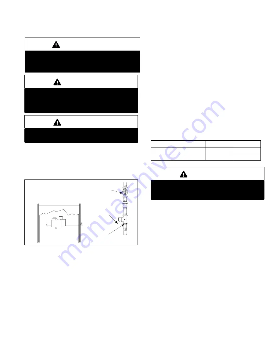
When pressure testing gas lines, the gas valve must be dis-
connected and isolated. Gas valves can be damaged if
subjected to more than 0.5psig (14" W.C.). See figure 19

If

the pressure is equal to or less than 0.5psig (14"W.C.), use
the manual shut−off valve before pressure testing to isolate
furnace from gas supply.

FIGURE 19

MANUAL MAIN SHUT−OFF VALVE

WILL NOT HOLD TEST PRESSURE

IN EXCESS OF 0.5 PSIG (14"W.C.)

GAS VALVE

CAP

GAS PIPING TEST PROCEDURE

FIELD PROVIDED

LINE PRESSURE TAP

When checking piping connections for gas leaks, use pre-
ferred means. Kitchen detergents can cause harmful corro-
sion on various metals used in gas piping. Use of a specialty
Gas Leak Detector is strongly recommended. It is available
through Lennox under part number 31B2001. See Corp.
8411−L10, for further details.

Do not use matches, candles, flame or any other source of
ignition to check for gas leaks.

D−Testing Gas Supply Pressure

When testing supply gas pressure, connect test gauge to
inlet pressure tap (field provided). See figure 19. Check gas
line pressure with unit firing at maximum rate. Low pres-
sure may result in erratic operation or underfire. High pres-
sure can result in permanent damage to gas valve or over-
fire. See table 12 for operating pressure at unit gas connec-
tion (line).

On multiple unit installations, each unit should be checked
separately, with and without units operating. Supply pres-
sure must fall within range listed in previous paragraph.

E−Check Manifold Pressure

After line pressure has been checked and adjusted, check
manifold pressure. Move pressure gauge to outlet pres-
sure tap located on unit gas valve (GV1). Checks of man-
ifold pressure are made as verification of proper regulator ad-
justment. Manifold pressure for the G40UH(X) can be mea-
sured at any time the gas valve is open and is supplying gas
to the unit. See table 12 for normal operating manifold pres-
sure.

TABLE 12

All G40UH Units

Natural

LP

Line Pressure WC"

4.5 − 10.5

11.0 −  13.0

Manifold Pressure WC"

3.5

10.0

IMPORTANT

For safety, connect a shut-off valve between the
manometer and the gas tap to permit shut off of
gas pressure to the manometer.

The gas valve is factory set and should not require adjust-
ment. All gas valves are factory regulated.  See specifica-
tions section of this manual for High Altitude manifold pres-
sure settings.

Manifold Adjustment Procedure:

1 − Connect a test gauge to outlet pressure tap on gas

valve. See figures 16, 15 and 17. Start unit and allow 5
minutes for unit to reach steady state.

2 − While waiting for the unit to stabilize, notice the flame.

Natural gas should burn blue. L.P. gas should burn
mostly blue with some orange streaks.

3 − After allowing unit to stabilize for 5 minutes, record

manifold pressure.

NOTE−Shut unit off and remove manometer as soon as
an accurate reading has been obtained. Take care to re-
place pressure tap plug.

Summary of Contents for G40UHX Series

Page 1: ...not supersede or replace local or state codes In the absence of local or state codes the guidelines and procedures outlined in this manual except where noted are recommended only and do not constitut...

Page 2: ...35 G40UH 60D 155 g Performance Low NOx Model No 60C 110X Input Btuh 110 000 110 000 110 000 132 000 132 000 154 000 Output Btuh 90 200 88 500 89 400 106 900 106 900 124 700 2 AFUE 80 0 80 0 80 0 80 0...

Page 3: ...33 62D 2F Horizontal CH33 36C 2F CH33 48C 2F CH33 50 60C 2F CH33 60D 2F CH33 62D 2F Electrical characteristics 120 volts 60 hertz 1 phase less than 12 amps OPTIONAL ACCESSORIES MUST BE ORDERED EXTRA A...

Page 4: ...with 1 in 25 mm cleanable filter not furnished field provided in place Also see Filter Air Resistance table G40UH 24A 070 PERFORMANCE External Static Air Volume Watts at Various Blower Speeds Externa...

Page 5: ...0 930 440 405 780 370 335 0 40 100 1285 605 610 1140 540 475 900 425 390 745 350 325 0 50 125 1215 575 580 1080 510 450 865 410 375 705 335 310 0 60 150 1150 545 560 1015 480 430 810 380 355 655 310 2...

Page 6: ...555 1265 595 459 40 100 1820 860 699 1670 790 611 1470 695 525 1255 590 443 50 125 1740 820 664 1600 755 575 1420 670 496 1215 575 414 60 150 1635 770 624 1530 720 544 1350 635 464 1175 555 400 70 17...

Page 7: ...t with 1 in 25 mm cleanable filter not furnished field provided in place Also see Filter Air Resistance table G40UH 48C 135 PERFORMANCE External Static Air Volume Watts at Various Blower Speeds Extern...

Page 8: ...filter not furnished field provided in place Also see Filter Air Resistance table G40UH 60C 110 1 2 3 with 3 4 hp motor PERFORMANCE Single Side Return Air Air volumes in bold require field fab ricated...

Page 9: ...le filter not furnished field provided in place Also see Filter Air Resistance table G40UH 60C 110 with 1 hp motor PERFORMANCE Single Side Return Air Air volumes in bold require field fabricated trans...

Page 10: ...able filter not furnished field provided in place Also see Filter Air Resistance table G40UH 60D 135 1 2 3 with 3 4 hp motor PERFORMANCE Single Side Return Air Air volumes in bold require field fab ri...

Page 11: ...5 791 1545 730 656 30 75 2235 1055 1234 2045 965 914 1820 860 774 1540 725 642 40 100 2160 1020 1240 1985 935 886 1800 850 755 1540 725 628 50 125 2065 975 1170 1925 910 863 1745 825 726 1535 725 614...

Page 12: ...s Watts 00 0 2670 1260 1386 2325 1095 1048 1970 930 857 1700 800 706 10 25 2580 1215 1342 2320 1095 1045 1965 925 842 1690 795 696 20 50 2510 1185 1311 2255 1065 985 1960 925 817 1640 775 662 30 75 24...

Page 13: ...pressure regulator setting Manifold Pressure Outlet in w g kPa FUEL ALTITUDE ft m FUEL 0 10 000 0 3048 Natural Gas 3 5 87 LPG Propane 10 0 2 49 HIGH ALTITUDE G40UH 1 1 High Altitude Orifice Kit Natur...

Page 14: ...Orifices Ignitor Bracket Burner Bottom Shield Limit Shield Secondary Limit as required NOx Units Only G40UH X PARTS ARRANGEMENT FIGURE 1 Gas Manifold 135 and 155 kBtuh units only Flame rollout switch...

Page 15: ...GURE 3 G40UH X HEATING COMPONENTS COMBUSTION AIR INDUCER PROVE SWITCH PRIMARY LIMIT PRIMARY LIMIT SHIELD GAS VALVE ROLLOUT SWITCHES MANIFOLD BURNER ASSEMBLY NOx Insert NOx Units Only HEAT EXCHANGER FL...

Page 16: ...NG Shock hazard Disconnect power before servicing Control is not field repairable If control is inoperable sim ply replace entire control Can cause injury or death Unsafe operation will result if repa...

Page 17: ...f 35 seconds After a total of five trials for ignition including the initial trial the control goes into Watchguard Flame Failure mode After a 60 min ute reset period the control will begin the igniti...

Page 18: ...OFF Circuit board failure or control wired incorrectly OFF ON y FAST FLASH SLOW FLASH Main power polarity reversed Switch line and neutral SLOW FLASH FAST FLASH Low flame signal See Table 15 for flam...

Page 19: ...nal designations See table 4 for troubleshooting diagnostic codes The mini nitride ignitor is made from a non porous high strength proprietary ce ramic material that provides long life and trouble fre...

Page 20: ...ote the supply air temperature at the instant the blower is de energized Adjust the fan off delay to achieve a supply air temperature between 90 110 at the instant the blower is de ener gized Longer d...

Page 21: ...ion air inducer may be rotated clockwise or counterclockwise by 90 to allow for vertical vent discharge in a horizontal application Remove the four mounting screws rotate the assembly assembly consist...

Page 22: ...HP motors have 2 flat sides and are matched with blower wheels with 2 set screws 10 Primary Limit Control S10 The primary limit S10 on G40UH X units is located in the heating vestibule panel When exc...

Page 23: ...3 Combustion Air Inducer Proving Switch S18 G40UH X series units are equipped with a combustion air proving switch located on the combustion air inducer orifice bracket The switch is connected to the...

Page 24: ...utes to clear out any gas If you then smell gas STOP Immediately call your gas supplier from a neighbor s phone Follow the gas supplier s instruc tions If you do not smell gas go to next step 8 Honeyw...

Page 25: ...ck gas line pressure with unit firing at maximum rate Low pres sure may result in erratic operation or underfire High pres sure can result in permanent damage to gas valve or over fire See table 12 fo...

Page 26: ...ate reading shut off all other gas appliances connected to meter IMPORTANT For safety shut unit off and remove manometer as soon as an accurate reading has been obtained Take care to replace pressure...

Page 27: ...S A Blower Operation and Adjustment NOTE The following is a generalized procedure and does not apply to all thermostat controls 1 Blower operation is dependent on thermostat control system 2 Generally...

Page 28: ...ning furnace Cleaning the heat exchanger requires a steel spring snake a reversible drill and a vacuum cleaner The steel spring snake may be constructed by purchasing a 4 ft long by 1 4 diameter steel...

Page 29: ...section DO NOT BEND 15 Replace burner manifold assembly onto vestibule panel 16 Reconnect wires to pressure switch roll out switch gas valve and combustion air inducer Refer to unit wiring diagram 17...

Page 30: ...or control goes into 5 minute Watchguard Pressure Switch delay Once S18 closes a 15 second pre purge follows 4 SureLight control A92 energizes ignitor A 20 sec ond warm up period begins 5 Gas valve op...

Page 31: ...SECOND GAS VALVE OFF COMBUSTION AIR INDUCER ON INDOOR BLOWER ON HEATING SPEED LED 1 SLOW FLASH LED 2 OFF GAS VALVE OFF COMBUSTION AIR INDUCER OFF INDOOR BLOWER OFF WITH DELAY LED 1 OFF LED 2 SLOW FLA...

Page 32: ...GAS VALVE OFF COMBUSTION AIR INDUCER ON INDOOR BLOWER ON HEATING SPEED LED 1 SLOW FLASH LED 2 OFF GAS VALVE OFF COMBUSTION AIR INDUCER OFF INDOOR BLOWER OFF WITH DELAY LED 1 OFF LED 2 SLOW FLASH Seque...

Page 33: ...LOWER OFF HAS CONTROL FAILED TO SENSE FLAME FOR FIVE CONSECUTIVE TRIES DURING A SINGLE HEAT DEMAND WATCHGUARD MODE GAS VALVE OFF COMBUSTION AIR INDUCER OFF INDOOR BLOWER OFF WITH DELAY LEDs SIGNAL WAT...

Page 34: ...D SLOW FLASH RATE REMAINS UNCHANGED THROUGHOUT COOLING CYCLE THERMOSTAT CALLS FOR COOLING COMPRESSOR CONTACTOR AND SYSTEM FAN ENERGIZED WITH 0 SECOND DELAY COOLING SPEED EAC H TERM ENERGIZED COMPRESSO...

Page 35: ...S ENERGIZED THERMOSTAT CALLS FOR HEAT W THERMOSTAT CALLS FOR COOLING THERMOSTAT OPENS SYSTEM FAN SWITCHED TO COOL H SPEED EAC H TERM REMAINS ON THERMOSTAT OPENS CONTROL G ENERGIZES SYSTEM FAN AT HEAT...

Page 36: ...nto 5 minute Watchguard Pressure Switch delay Once S18 closes a 15 second pre purge follows 4 Ignition control A92 energizes ignitor A 20 second warm up period begins 5 Gas valve opens for a 4 second...

Page 37: ...INIMUM OF 1 SECOND GAS VALVE OFF COMBUSTION AIR INDUCER ON INDOOR BLOWER ON HEATING SPEED LED 1 SLOW FLASH LED 2 OFF GAS VALVE OFF COMBUSTION AIR INDUCER OFF INDOOR BLOWER OFF WITH DELAY LED 1 OFF LED...

Page 38: ...DE GAS VALVE OFF COMBUSTION AIR INDUCER OFF INDOOR BLOWER OFF WITH DELAY LEDs SIGNAL WATCHGUARD FAILURE CODE IS 60 MINUTE RESET PERIOD COMPLETE YES 4 SECONDS YES HAS CONTROL RESET IGNITION SEQUENCE FO...

Page 39: ...ROUGHOUT COOLING CYCLE THERMOSTAT CALLS FOR COOLING COMPRESSOR CONTACTOR AND SYSTEM FAN ENERGIZED WITH 2 SECOND DELAY COOLING SPEED EAC TERM ENERGIZED COMPRESSOR OFF THERMOSTAT OPENS SYSTEM FAN AND EA...

Page 40: ...ED THERMOSTAT CALLS FOR HEAT W THERMOSTAT CALLS FOR COOLING THERMOSTAT OPENS SYSTEM FAN SWITCHED TO COOL SPEED EAC TERM REMAINS ON THERMOSTAT OPENS MANUAL FAN SELECTION MADE AT THERMOSTAT CONTROL G EN...

Page 41: ...the top button ACTION 2 Determine the cause of the roll out switch activation before leaving furnace code LED 1 O 1 2 2 Roll out switch failure ACTION 1 Check continuity across roll out switch Replace...

Page 42: ...IT FAILS TO FIRE IN THE HEATING MODE COMBUSTION AIR BLOWER DOES NOT ENERGIZE Condition Possible Cause Corrective Action Comments 2 1 Unit operates with a cooling or contin uous fan demand Combustion a...

Page 43: ...a heating demand Diagnostic lights flash the pressure switch failure code 2 5 minutes after heating demand 3 1 2 Prove switch does not close due to obstructions in the pressure lines ACTION 1 Remove...

Page 44: ...e switch code LED 1 Off LED 2 Slow Flash 5 1 1 Low pressure differential at the prove switch ACTION 1 Check for restricted exhaust vent Remove all blockage ACTION 2 Check for proper vent sizing See in...

Page 45: ...exchanger openings Cor rect the location of the burners if necessary 5 4 Combustion air inducer energizes with a heating demand B li ht hl d th it 5 4 1 Poor Venting ACTION 1 Check vent pipe and remo...

Page 46: ...tion Comments 7 0 Indoor blower fails to operate in continuous fan cooling or heating mode 7 1 1 Miswiring of furnace or improper con nections at control or indoor blower motor ACTION 1 Correct wiring...

Reviews: