Page 5
5– “24V” Terminal
Terminal “24V” receives 24VAC from the control
transformer through the defrost thermostat. This
terminal powers the control’s internal timer and
relays. Terminal “24V” is powered only when there
is a call for defrost (defrost thermostat closed). The
timer begins timing at 0 only after terminal “24V”
receives power.
6– “OUT” Terminal
Terminal “OUT” controls defrost when connected
to one side of the defrost relay coil. An internal
relay connected to terminal “OUT” closes to allow
external defrost relay to energize and initiate
defrost. At the end of the defrost period, the
internal relay connected to terminal “OUT” opens
to de-energize the external defrost relay.
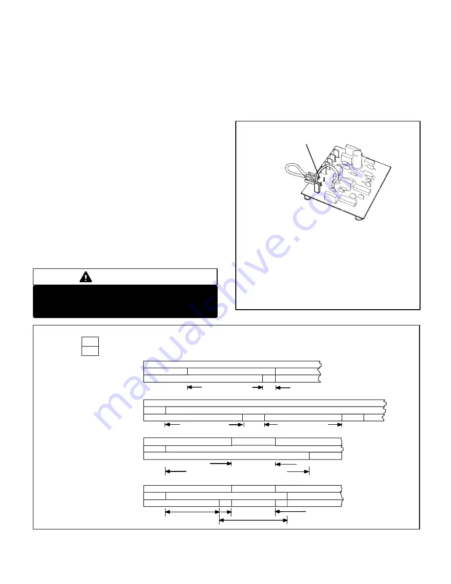
7– “TST” Pins
Each board is equipped with a set of test pins for
use in troubleshooting the unit. When jumpered
together, these pins reduce the control timing to
about 1/256 original time (see table 3 and figure 6).
IMPORTANT
Control will begin test mode only if normal load is
applied to control terminals. Do not attempt to
operate or test control out of unit.
A defrost period can last up to 14 minutes and can be
terminated two ways. If the defrost thermostat does
not open within 14 minutes after defrost begins, the
timer will de–energize the defrost relay and the unit
will resume normal operation. If the defrost
thermostat opens during the 14 minute defrost period,
the defrost relay is de–energized and the unit resumes
normal operation. Refer to figure 7.
FIGURE 6
WARNING – AVOID CONTACT WITH OTHER CONTROL
TERMINALS OR CONTROL COMPONENTS.
TO PLACE CONTROL IN TEST MODE:
1– Turn off all power to avoid damaging the circuit board.
2– Make sure all control terminals are connected as shown on
unit wiring diagram before attempting to place control in
test mode. See NOTE below.
NOTE – Control will not go into test mode when discon-
nected from unit. Unit load must be applied to control termi-
nals before the control will go into test mode.
3– Connect jumper to “TST” pins as shown.
4– Turn indoor thermostat to heat mode and adjust to highest
temperature setting.
5– Turn on power to unit.
6– See Table 3 for control timings in “TST” mode.
7– Be sure to turn off power and remove jumper when test is
complete. Turn on power and re–adjust thermostat.
DEFROST CONTROL TEST MODE
ÉÉÉÉÉÉÉÉÉÉÉÉÉÉÉÉÉ
ÉÉÉÉÉÉÉÉÉÉÉÉÉÉÉÉÉ
ÉÉÉÉÉÉÉÉÉÉÉÉÉÉÉÉÉ
ÉÉÉÉÉÉÉÉÉ
ÉÉÉÉÉÉÉÉÉ
ÉÉ
ÉÉÉÉÉÉÉÉÉÉÉÉÉÉÉÉÉÉÉÉÉ
ÉÉÉÉÉÉÉÉÉÉÉÉÉÉÉÉÉÉÉÉÉ
ÉÉÉ
ÉÉÉ
ÉÉÉ
ÉÉÉ
ÉÉÉÉÉÉÉÉÉ
ÉÉÉÉÉÉÉÉÉ
ÉÉÉÉÉÉÉ
ÉÉÉÉÉÉÉ
ÉÉÉÉ
ÉÉÉÉ
ÉÉÉÉÉÉÉÉÉ
ÉÉÉÉÉÉÉÉÉ
ÉÉÉÉÉÉÉ
ÉÉÉÉÉÉÉ
ÉÉÉÉÉÉÉÉÉÉÉÉ
ÉÉÉÉÉÉÉÉÉÉÉÉ
ÉÉ
ÉÉ
ÉÉ
ÉÉ
CLOSED, ON
OPEN, OFF
THERMOSTAT DEMAND
DEFROST THERMOSTAT
DEFROST RELAY
DEFROST THERMOSTAT
DEFROST RELAY
THERMOSTAT DEMAND
DEFROST THERMOSTAT
DEFROST RELAY
THERMOSTAT DEMAND
DEFROST THERMOSTAT
DEFROST RELAY
10HP SERIES UNITS TYPICAL DEFROST TIMINGS
NORMAL HEATING OPERATION: DEFROST TERMINATED BY DEFROST THERMOSTAT
NORMAL HEATING OPERATION: DEFROST TERMINATED BY TIME
NORMAL HEATING OPERATION INTERRUPTED BY THERMOSTAT DEMAND: “HOLD” FUNCTION
DEFROST PERIOD INTERRUPTED BY THERMOSTAT DEMAND: “HOLD” FUNCTION
30/60/90 MINUTES
“HOLD” TIME
“HOLD” TIME
14 MIN. PLUS “HOLD” TIME
30/60/90 MINUTES
DEFROST THERMOSTATOPEN WITHIN 14 MINUTES
30/60/90 MINUTES
14 MIN.
30/60/90 MINUTES
30/60/90 MINUTES PLUS “HOLD” TIME
Note – Control begins timing at 0 when defrost thermostat closes. Defrost is terminated when defrost
relay is de–energized. Anytime defrost thermostat opens, defrost relay is immediately de–energized,
defrost timer resets and “HOLD” function stops.
DEFROST THERMOSTAT
MUST REMAIN CLOSED
FOR TIMER TO REMAIN
IN “HOLD”
DEFROST THERMOSTAT
MUST REMAIN CLOSED
FOR TIMER TO REMAIN
IN “HOLD”
FIGURE 7
ÉÉÉÉÉÉÉÉÉÉÉÉÉÉÉÉÉÉÉÉÉÉÉ
THERMOSTAT DEMAND


