


Trimod®
Oper
ating and M
ain
tenanc
e M
anual
37
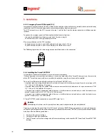
To ensure that the UPS Trimod® has stopped completely if you want to add a Trimod® BATTERY in an existing installation,
follow the steps illustrated in the MAINTENANCE chapter.
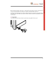
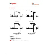
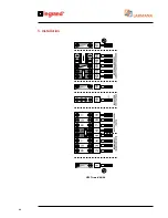
The connection of a Trimod® BATTERY to the UPS Trimod® must be done according to the following diagram and the steps
listed below:
1. Make sure that all the battery fuse carrier isolating switches are open;
2. Connect the UPS and the additional battery cabinet using the earth cable (yellow-green);
3. Use the wiring supplied with the Trimod® BATTERY to connect the positive and negative terminals of the UPS Trimod®
to those of the Trimod® BATTERY.
UPS
Trimod
®
BATTERY
UPS
Trimod
®
BATTERY
UPS
Trimod
®
Summary of Contents for Trimod 10 kVA
Page 1: ...Trimod Operating and Maintenance Manual Part LE05768AA 07 12 01 GF ...
Page 2: ... 2 EN ENGLISH 3 Trimod ...
Page 12: ...12 UPS Trimod 10 UPS Trimod 10 15 20 2 3 Models 2 Technological description ...
Page 13: ...Trimod Operating and Maintenance Manual 13 UPS Trimod 10 15 20 UPS Trimod 30 TT ...
Page 14: ...14 UPS Trimod 30 TM UPS Trimod 40 2 Technological description ...
Page 15: ...Trimod Operating and Maintenance Manual 15 UPS Trimod 60 ...
Page 16: ...16 2 Technological description UPS Trimod BATTERY UPS Trimod BATTERY 2 ...
Page 42: ...42 5 Installation UPS Trimod 30TM ...
Page 43: ...Trimod Operating and Maintenance Manual 43 UPS Trimod 30TT ...
Page 44: ...44 UPS Trimod 40 60 5 Installation ...
Page 46: ...46 5 Installation ...


