


10
®
Advantages:
- A UPS with a modular redundant architecture can be con
fi
gured as an N+X system redundant in power; even in the
case of a failing module the equipment carries on working and there is no stop in work.
- Clear indications and a large display speed up troubleshooting.
- The modular architecture makes short work of repairing a failure by simply replacing the module in question without
interrupting service.
- A high resolution percentage of failures at the
fi
rst assistance intervention.
Power module
The basic module, available in three power sizes, 3,400 VA, 5,000 VA and 6,700 VA, is basically made up of the following
functional blocks: command and control logic (microprocessor controlled), recti
fi
er/PFCr, inverter, booster, battery
charger, automatic bypass.
The power unit is the Plug & Play type to facilitate power expansion and all maintenance works. Each module is paralleled
with other identical ones until the UPS power is reached.
The power modules are separate from each other and can work even if one malfunctions. A LED on the front of the
module, with a tra
ffi
c-light code, quickly shows the operating state of the electronic unit.
Prescription forms for PM4, PM6 and PM7
only on the related cabinets: UPS Trimod® electrical distribution equipment
is sized for its nominal power and must be used only with power modules originally installed.
Each cabinet must use only the provided power modules, described in table "Mechanical properties" on page 18 of this
manual. It is not possible to use power modules other than those indicated, nor mix with other models and/or replace
the type of modules.
• The model, the power rating and the type of power module to be installed in the UPS cabinet UPS Trimod® are indicated
on the user manual and on the label inside the door of the UPS.
• The type and power rating of the power module are indicated on the label a
ffi
xed to the bottom of the power module
for proper identi
fi
cation.
It is recommended to use only provided UPS Trimod® Power Modules.
Battery drawers
The battery modules are designed for easy insertion in the cabinet with no work needed to connect them; they are easy
to handle thanks to their light weight, likewise any maintenance or replacing.
A box holds 5 12V, 7.2 Ah or 9 Ah batteries connected in series and, thanks to the Plug & Play connection can be easily
pulled out and put inside the cabinet. In order to guarantee maximum safety, especially during maintenance, the voltage
of each box is adequately disconnected into two 24 and 36V branches and restored only when the box is placed right
inside its housing. This conforms to the CEI-EN 60950 standard on electrical safety which establishes that adequate
safeguards must be used and particular attention where there are dangerous voltages higher than 50 Vdc with the
possibility of direct contact.
Autonomy can be increased further still by adding other battery ‘boxes’ in multiples of four,
exploiting the space inside the UPS and the space in the additional ‘modular cabinets
Digital display and displaying alarms
Trimod® is controlled by a microprocessor and has a backlit alphanumerical liquid crystal display (LCD) with 20 characters
on 4 lines built into the front of the UPS where there is also a highly luminous operating status indicator which, by means
of a tra
ffi
c-light code, indicates the operating status and any alarm conditions.
Four simple push buttons near the display allow the user to: see operating data, set operating parameters, analyse the
state of each single power module, select the language in which to see the messages and execute a set of functional tests.
BCM (Battery Charger Module)
It works together with internal PM chargers, with the same intelligent management of the charging cycle. For each BCM
installed the maximum batteries recharging current is increased of 15Adc: 1 BCM has a charging current equivalent to
that of 6 (internal to the charger) PMs. This guarantees to reduce charging time in installations that require long backup
time UPS and increases the availability of the UPS system after a power failure (blackout).
During operation, the module draws current from the phase input (slot) in which it is installed. If at least n°1 PM is present,
it is possible to install any number of BCM.
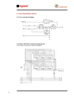
2. Technological description
Summary of Contents for Trimod 10 kVA
Page 1: ...Trimod Operating and Maintenance Manual Part LE05768AA 07 12 01 GF ...
Page 2: ... 2 EN ENGLISH 3 Trimod ...
Page 12: ...12 UPS Trimod 10 UPS Trimod 10 15 20 2 3 Models 2 Technological description ...
Page 13: ...Trimod Operating and Maintenance Manual 13 UPS Trimod 10 15 20 UPS Trimod 30 TT ...
Page 14: ...14 UPS Trimod 30 TM UPS Trimod 40 2 Technological description ...
Page 15: ...Trimod Operating and Maintenance Manual 15 UPS Trimod 60 ...
Page 16: ...16 2 Technological description UPS Trimod BATTERY UPS Trimod BATTERY 2 ...
Page 42: ...42 5 Installation UPS Trimod 30TM ...
Page 43: ...Trimod Operating and Maintenance Manual 43 UPS Trimod 30TT ...
Page 44: ...44 UPS Trimod 40 60 5 Installation ...
Page 46: ...46 5 Installation ...